Show messages:
1-15
16-35
36-55
56-75
76-95
96-113
From: Michael Gibson
Hi Michel,
re:
> To avoid possible confusion with visible lines when printing screenshots in black & white, do you
> think you'll be able to insert a small gap between dimension elements (extension lines, arrows)
> and objects?
So something like this for the extension lines? :

For the gap on arrows, would that also apply to the arrows going to the extension lines in a linear dimension like above, or only to the arrows on other dimension types?
I'm not sure if I'll be able to do an arrow gap on angular dimensions because that would also involve trimming back some of the arc that is being drawn, but I could do it for radial and leader dimension types.
- Michael
Image Attachments:
 Mip_gap.jpg
From: bemfarmer
ecabinetsystems has some discussion about 3D dimensions here:
http://order.ecabinetsystems.com/updates/ecabinetsystemsmadeeasy/Dimensioning_in_3D.htm
They use red dimension lines with blue arrows for 3D, but do have some warnings about confusion.
I particularly liked the drawing and anatomy at this link:
https://www.3dhubs.com/knowledge-base/how-prepare-technical-drawing-cnc-machining
I guess several MoI drawings would need to be combined in pdf?
The link "angle projection" goes to "Multiview projection-Wikipedia."
- Brian
From: James (JFH)
Michael,
I greatly appreciate the efforts you have gone to on this.
Maybe Karsten's solution then is the best way to go, but only if his cone arrowheads could be made to be scale independent (ie always small).
Another possible work around would be to have 2 perpendicular associated planes with each vector, like shown below, however with only one arrow displayed at any one time. The display would be triggered on/off (or off/on) based on angle of incidence to screen view.

Again thanks you so much for looking to solve this
James
https://www.instagram.com/nodeology/
PS the work you have done to date for display "flat to screen" will find utility with the "Numbering" node
Image Attachments:
arrowHead.gif
From: Michael Gibson
Hi Brian,
> I guess several MoI drawings would need to be combined in pdf?
Something like that would really need some other software rather than MoI. The new dimensions in MoI will be useful for simple cases and light duty but not really for making detailed production drawings like that example.
Various other CAD software have a much more extensive drawing toolset to help make that type of output.
- Michael
From: Frenchy Pilou (PILOU)
Can we move, orient (align) , size the "Blah" text ? (after draw the arrow lines)
Does the "Blah" text has some of these 3 functions as "native" ones when you draw the arrow lines?
and something like "out" (begin, end) "cut" (when inside) arrow lines?
From: Mik (MIKULAS)
MOI + Make2D4Views script (
http://moi3d.com/forum/index.php?webtag=MOI&msg=8041.1 ) exported in DXF + free SOLID EDGE 2D DRAFTING (
https://www.plm.automation.siemens.com/plmapp/education/solid-edge/en_us/free-software/free-2d-cad ) = perfect results for technical drawing.
Only thing it has to be done is alignment of views according to appropriate standard - US vs EU (
http://moi3d.com/forum/index.php?webtag=MOI&msg=8041.19 )
Ciao
Mik
From: Finema
even simpler....
MOI + ONSHAPE (free)
Import my MoI .3dm file in Onshape and apply Menu > Create drawing of 3dm
From: Michael Gibson
Hi Pilou,
re:
> Can we move, orient (align) , size the "Blah" text ? (after draw the arrow lines)
I'll probably try to have an option for moving it but align or sizing is not likely.
> Does the "Blah" text has some of these 3 functions as "native" ones when you
> draw the arrow lines?
Sorry I don't understand this part.
>and something like "out" (begin, end) "cut" (when inside) arrow lines?
I'm going to be working on having text cut the arrow line, the text part is still not finished yet.
- Michael
From: Michael Gibson
Hi James,
re:
> Another possible work around would be to have 2 perpendicular associated planes with each vector,
> like shown below, however with only one arrow displayed at any one time. The display would be triggered
> on/off (or off/on) based on angle of incidence to screen view.
I gave this a try, here's what it looks like:
Doesn't seem too satisfying in removing planar feel to it, if you pause the video at various spots things still seem pretty planar.
- Michael
From: James (JFH)
Michael,
On the contrary, I think it is most satisfactory. Vectors after all are just aids for visualising spatial constraint in the construction process; not for final output.
Thank you so much, brilliant work
James
From: Michael Gibson
Hi James, ok well it's a quite localized tweak to get that behavior so it should be fine to have a script property on annotation objects that will make it behave like that when set.
Those ones shown in the last video are Leader objects with 2 points.
- Michael
From: Frenchy Pilou (PILOU)
> Does the "Blah" text has some of these 3 functions as "native" ones when you
> draw the arrow lines?
<< Sorry I don't understand this part.
When you draw your "arrows" does the Text is yet configured for have definited Size, Align (up, down,on), Distance etc... or it's after draw?
Or we can take the "Blah" as an normal object for make any what you want...
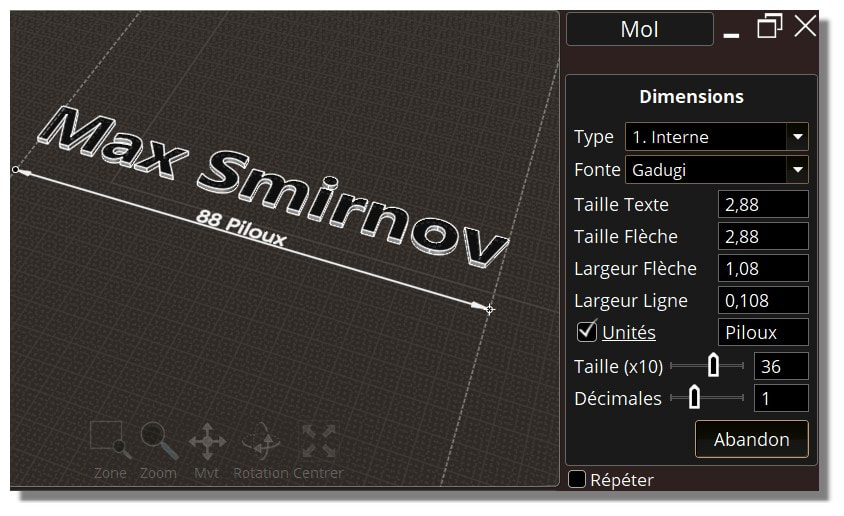
But I am not impatient! :) Because there is yet a cool one by Max Smirnov! ;)
http://moi3d.com/forum/index.php?webtag=MOI&msg=7403.133
From: Michael Gibson
Hi Pilou,
re:
> When you draw your "arrows" does the Text is yet configured for has definited Size, Align (up, down,on),
> Distance etc... or it's after draw?
Neither - the text is displayed as a text label on screen more like the object snap tags like "End", "Mid", etc... so it gets its size from the regular UI font size.
- Michael
From: Mip (VINC)
Hi Michael,
Thanks, the extension lines would be fine with that gap.
>For the gap on arrows, would that also apply to the arrows going to the extension lines in a linear dimension like above,
>or only to the arrows on other dimension types?
The arrows can touch the shapes and the extension lines as there is no ambiguity for the reader but the actual ones slightly cross the shapes.
Thanks,
Michel
From: Rudl
When will we get the dimension tool. I think everybody here is full of expectation.
From: Michael Gibson
Hi Michel, the arrowhead points do have a few pixels sticking out past the lines, that's due to its wire outline being drawn with mitered corners and anti-aliasing.
You can see the same thing in regular curves in MoI if you just make a line and a pointy triangle:

Max's one doesn't do that because it makes a surface for the arrowhead and surface trim boundaries are not drawn with mitered corners between segments.
If this is troublesome I guess I could make a setting to not miter the arrowhead tip.
- Michael
Image Attachments:
Mip_miter.jpg
From: Michael Gibson
Hi Rudl,
> When will we get the dimension tool. I think everybody here is full of expectation.
It will be in the next v4 beta which will probably be the last one.
I've got just a couple more areas to finish them - text display and export to PDF/AI/DXF formats.
- Michael
From: Mip (VINC)
Hi Michael,
>Max's one doesn't do that because it makes a surface for the arrowhead
>and surface trim boundaries are not drawn with mitered corners between segments.
>If this is troublesome I guess I could make a setting to not miter the arrowhead tip.
Thanks for the explanation.
I would prefer the drawing to be as sharp as possible when adding dimensions if it's not too hard or heavy on display performance.
Michel
From: Michael Gibson
Hi James, here's a different variation on the arrowhead reorienting. This one turns the plane around the arrowhead direction to point as much as possible towards the view direction.
I tried this before but I guess I had something wrong. What do you think, better or worse than the one that switches between 2 planes? :
- Michael
From: James (JFH)
Michael,
>> better or worse....? <<
Not just better, it is exactly what I originally requested.
Absolutely Brilliant!
Thank you so much
James
https://www.instagram.com/nodeology/
Show messages:
1-15
16-35
36-55
56-75
76-95
96-113