Show messages:
1-4
…
185-204
205-224
225-244
245-264
Thread Split: Some posts in this thread have been moved here
From: Michael Gibson
Hi Barry, can you show me what yours looks like?
Over here my v4 looks like this:

And my V3 one looks like this:

- Michael
Image Attachments:
 PropertiesPanelStyleV3.jpg
PropertiesPanelStyleV4.jpg
PropertiesPanelStyleV3.jpg
PropertiesPanelStyleV4.jpg
From: Barry-H
Hi Michael,
this one.
Barry
.png)
Image Attachments:
Screenshot (271).png
From: coi (MARCO)
ahoy,
v4(right one) seems actually bigger/larger than v3..at least on my screen..windows 10

From: Michael Gibson
Hi Barry, hmm well that dialog is actually displayed by a Windows operating system call, it's a little different than other dialogs in MoI.
MoI v3 did make a custom template for the dialog that re-arranged things a bit like moving the custom colors off screen, I guess I also made the color squares slightly larger. MoI v4 just uses the default one given by Windows.
I guess it might be possible for me to have an option to use the same one as v3 did, I'll see about that.
- Michael
From: Barry-H
Hi Marco,
this is mine on Surface Pro 4.
Cheers
Barry
.png)
Image Attachments:
Screenshot (271).png
From: coi (MARCO)
ah i see. well, you've got a 3k device there, which might generate some scaling issues in win 10. i dunno if michael can adress this within the system call.
From: Tover (TOVERMORAN)
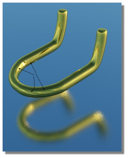
Hi, I'm a new Mo-I user so please excuse me if this feature suggestion is covered in a plugin/script.
The idea is to add more snapping options in line curve drawing mode, which are sensitive to their nearby points.
For example:

-- so as the cursor adds a new point, Moi3d suggests an alignment point with similar vertical placement, drawing a dashed line like the one I've drawn in magenta. It could detect any kind of angled line extensions, as with the cyan dashed line.
I've used other programs with similar functionality; it is super helpful for fast construction. I realise you can do this by manually adding construction lines as in traditional tech drawing -- this is a faster alternative.
Cheers.
PS absolutely loving the interface design and functionality of this program. Great work Michael!
Image Attachments:
smart-align.jpg
From: Michael Gibson
Hi Tover, I'm glad you are liking MoI!
So the construction lines function is what MoI has for that kind of functionality. And just to make sure - that doesn't just mean drawing additional regular lines, you can create what MoI calls a "construction line" while you are in any drawing command by holding down the mouse and dragging away from the point of interest.
There is more information here:
http://moi3d.com/3.0/docs/moi_command_reference11.htm#constructionlines
Having such lines appear in an automatic way works well for sparse drawings when you are drawing just a few lines like you show there. But when things are denser it becomes frustrating because your working area fills up with snaps all over and it can interfere with freely placing a point. So to avoid that MoI is intentionally designed to not do those automatically, only when you generate a construction line which can be done with a quick gesture inside any drawing command.
- Michael
From: overthere
Hi Michael,
For the SubD conversion feature is it expected behaviour that when the NURBS objected generated has a boolean subtraction performed on it in MOI the edges generated from that can't be filleted without errors?
I'm trying to work out if I'm making a mistake or just expecting too much from the feature.
Thanks
Andy
From: Tover (TOVERMORAN)
Hi Michael,
thanks for the detailed response! Sorry, I hadn't got deep enough into the docs yet. The construction lines function is such an elegant approach to this concept.
Rock on,
T
From: Michael Gibson
Hi Andy,
> For the SubD conversion feature is it expected behaviour that when the NURBS objected generated has a
> boolean subtraction performed on it in MOI the edges generated from that can't be filleted without errors?
> I'm trying to work out if I'm making a mistake or just expecting too much from the feature.
Well it depends on the situation. In general that is not expected, however also filleting in MoI can have problems with complex chaotic geometry and it is pretty easy to have complex chaotic geometry with SubD conversions.
Is it possible for you to post the model so I can take a look at it? If you want to keep it private you can e-mail it to me at
moi@moi3d.com, if it is very large you would need to use a file sharing service like Dropbox/OneDrive/etc... and send just a shared link through e-mail.
- Michael
From: Lordfox
Helo dear Micheal & dear users of Moi3D 4.0 (beta) ...
Is it possible, to import an OBJ too but without SUB-D?! Any possibility to set the strength of the build-in-SUBD? And for some OBJ Objects I dont want have SUBD ... e.g. if I import a pose from DesignDoll - nice tool for posing, but the poly-mesh-structure is very weird, lot of tris and so on - SUBD will not work well or much too long.
I try also the old MaxSmirnov Plugin _ImportOBJ it still works in 4.0 too, but in my eyes not very perfect, because if I import with _ImportOBJ the edges of each polygon are not welded, they are naked.
From: Michael Gibson
Hi Lordfox,
> Is it possible, to import an OBJ too but without SUB-D?!
Sorry, no not with any built in tools. An OBJ file without Sub-D is a faceted polygon mesh model and MoI is not designed to work with that kind of data for modeling. You would need to use a polygon mesh modeling program to import and work with that type of data, not MoI.
> Any possibility to set the strength of the build-in-SUBD?
Sorry, no not currently, it just uses the standard Catmull-Clark approach. At some point in the future I do want to add some edge weighting options but that would be unusual to do that directly in the OBJ importer.
> And for some OBJ Objects I dont want have SUBD ... e.g. if I import a pose from DesignDoll - nice tool
> for posing, but the poly-mesh-structure is very weird, lot of tris and so on - SUBD will not work well or
> much too long.
That model data is just not suitable for use in MoI in general - it's not what MoI is focused on working with.
- Michael
From: Lordfox
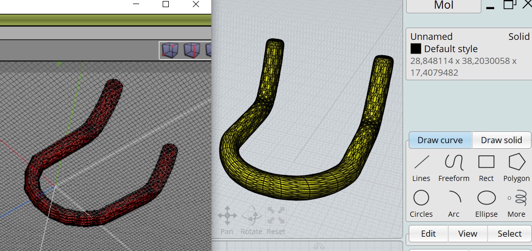
Hi, thanx ... but it runs good - the new SubD fuction - I have made some bevels in a polygon-modeling tool. Thank you so much. But one Polygon-Object I cant load with the SubD Tool. I dont know why, its very simple, no holes, only quads (754 Vertices) ... hmmm I dont know .... created in Silo 2.5.5.
http://www.mediafire.com/file/h04eys1g8e9mtc4/Rohr.obj/file => Rohr.OBJ thats the Missing Part
This OBJ I can also create in moi very easy and fast ... but please tell my, why I cant load.
Looks very well
https://i.imgur.com/gf9b82j.jpg
The guy I dont want import by SubD, but I can't import the thing between the seat and the ground. Im confused. Maybe a bug in the Beta Release? Or an issue with Silo?!
From: Frenchy Pilou (PILOU)
Ok That works with Wings 3D! ;)
(ps when you have such single object put it at the origine and not at the out of space! ;)
But your file has curious colors in some other free prog MeshLab, MeshMixer...
Here the OBJ...http://moiscript.weebly.com/uploads/3/9/3/8/3938813/rohr4.obj
And for this simple object you have better time to redraw it in Moi! ;)
Because 2 Millions polys at Maximum export is maybe not a cool deal! :).
And seems your model has some defaults...
From: bemfarmer
The two ends of the tubes have triangles, and T vertices.
By importObj script, and splitting the ends triangles, and saving, the tube will subD, but the ends are still polygons...
- Brian
From: Lordfox
@Pilou
I dont understand, why you see 2 Million Polys? But thanx, I will try out other pivot-settings.
@bemfarmer
thank you too - so I will take look to this too
I'm happy now .. it was my fail - did overwork the tube-ends. Now ist fine ...
https://i.imgur.com/ByHQ19d.jpg
From: Frenchy Pilou (PILOU)
When you import it by SUbD inside Moi
then export it as obj you have a choice to 67 000 (mini) to 2 000 000 polys (maxi) ;)
From: Michael Gibson
Hi Lordfox,
re:
> But one Polygon-Object I cant load with the SubD Tool. I dont know why, its very simple, no holes,
> only quads (754 Vertices) ... hmmm I dont know .... created in Silo 2.5.5.
It's because there are errors in the mesh structure, some degenerate faces and some faces with inconsistent normal directions.
The Rhino check command says:
quote:
This is a bad mesh.
Here is what is wrong with this mesh:
Mesh has 4 degenerate faces.
Important things to consider with this mesh:
Mesh has 128 faces with directions different from the mesh as a whole. Although this does not
necessarily mean that the mesh is bad, it can cause problems if you're doing mesh boolean operations with it.
Mesh has 4 pairs of faces that intersect each other. Although this does not
necessarily mean that the mesh is bad, it can cause problems if you're doing mesh boolean operations with it.
You may be able to fix it by using the "unify normals" tool in Silo:
https://nevercenter.com/silo3d/wiki/index.php?title=Unify_Normals
In the next v4 beta which should be released just later today, the sub-d conversion will skip over the problematic faces and give this result:

- Michael
Image Attachments:
lordfox_subd_import.jpg
From: Lordfox
Thanx ;) - so its a problem of silo, wrong faced polygons in silo sometimes black and I see it and I fix it, but in somtimes my silo-object looks clean and the wrong polygon(s) are not "black" in silo.
I will set a wacom key, that makes all faces unify and after this a save.
Show messages:
1-4
…
185-204
205-224
225-244
245-264