Show messages:
1-4
…
445-464
465-484
485-504
505-524
525-544
545-564
565-584
…
645-656
From: Frenchy Pilou (PILOU)
@ Peer ... SVG : it's a little nightmare! :)
I have maybe a process (in PDF) but we must hide these yellow lines by hand
so not sure that is a valid one that you have expected!
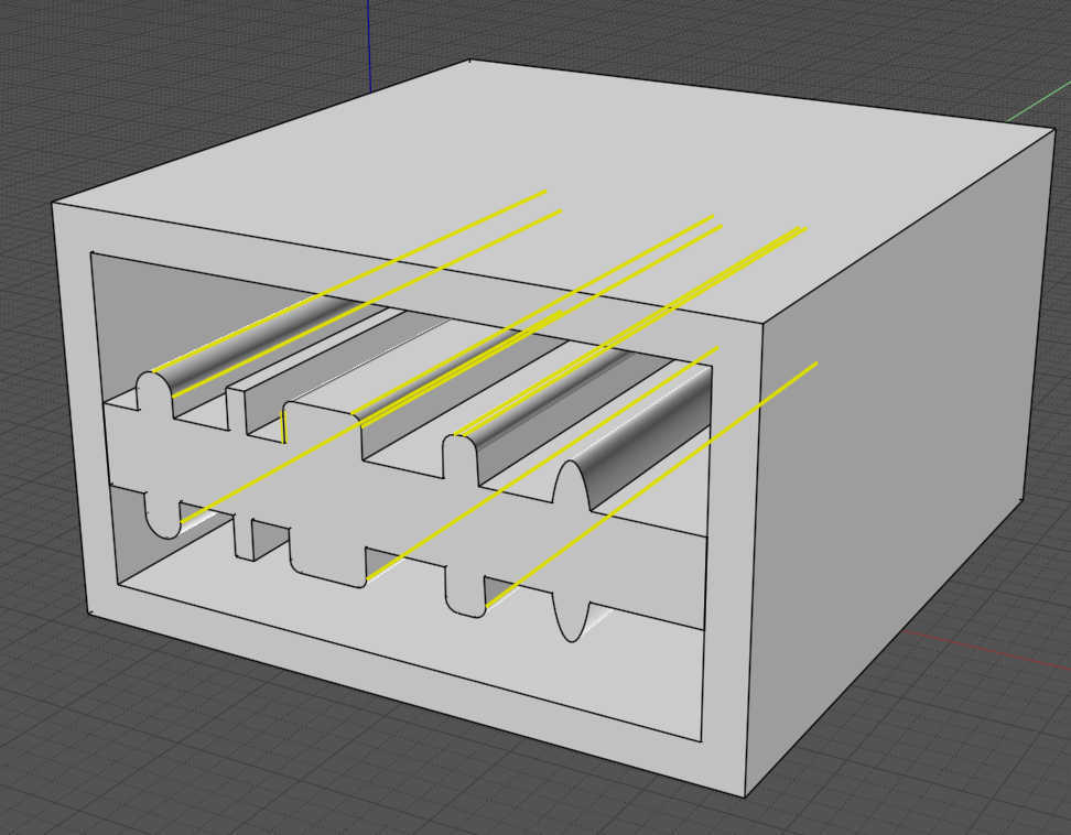
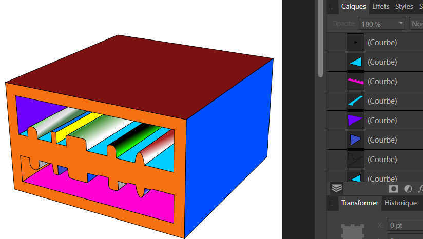
The Process some similar than previous !
From an Moi Object
- Boolean the solids
- Hide the lines no wanted
- Export as PDF View 3D for have any position wanted!
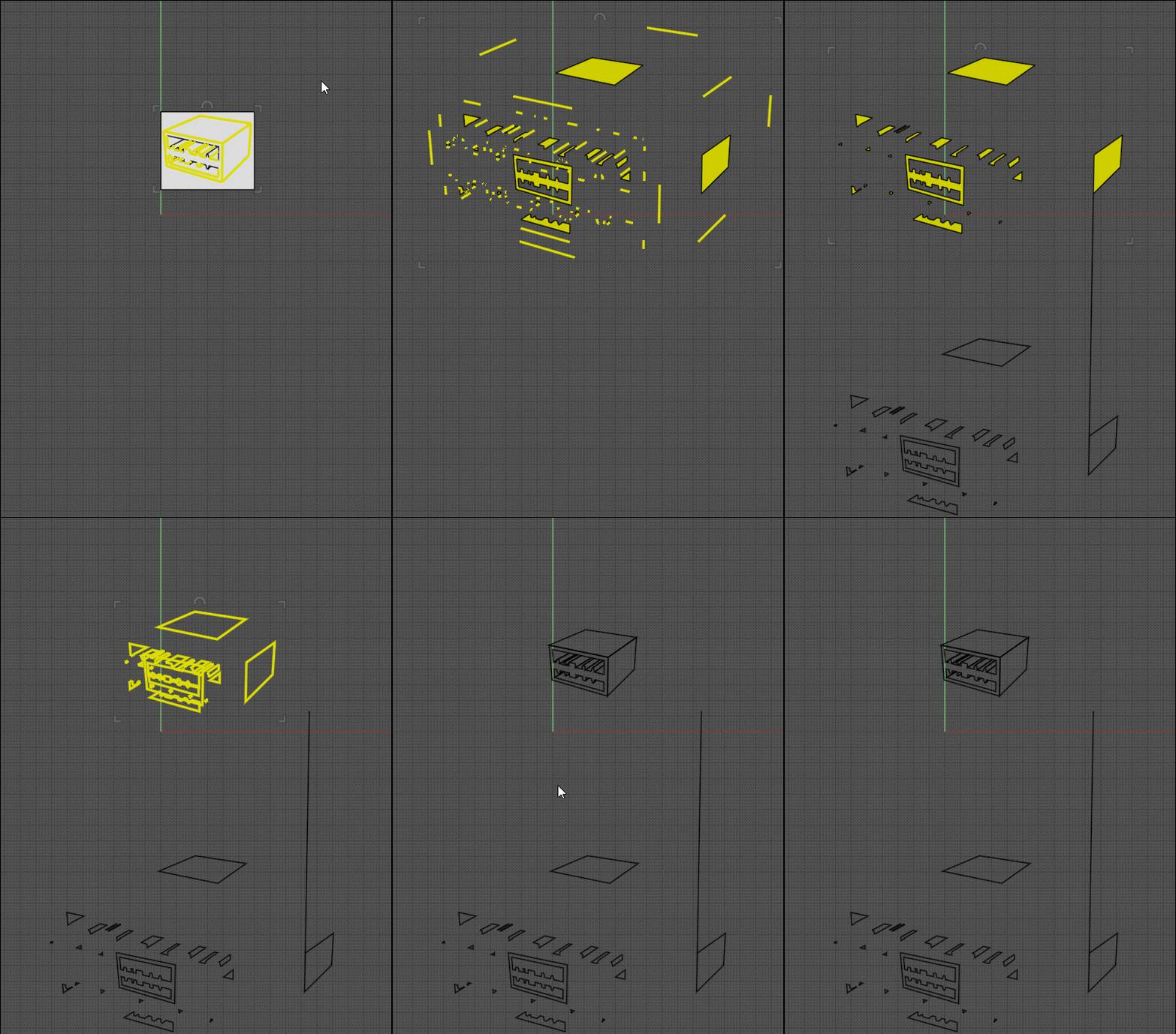
- New - Reload the PDF - View top (so we have the position of the original object in a plane ! )
- View Top - Intersect with a Plane
- Keep only the Object kill the rest
- the tricky Part! ExplodeMove (4)
- Select Curves (use the Browser) Kill them
- Select & Copy Move the Edges (use the Browser) become Curves! ) - Join these Curves = All curves are Closed!
- kill surfaces - put the closed curves at the original position
-UnExplode Move
- Export as PDF the closed curves View Top
- Open inside Affinity V1: colorize as you want all the Closed Curves!
et voilà! :)
to continue...but I leave the SVG for the moment too devious! :)
Else something like that :)
From: pressure (PEER)
Hi Pilou,
I tried to follow your instructions, but it doesn't really work for me. Here's what I see if I open closed_paths_test.pdf:

Also, even if this method works, it involves exporting an SVG from MoI, importing back into MoI to make closed paths, exporting from MoI again, and then combining the first export with the second export because the first export has multiple line widths that I need to keep. That's not really better than using Illustrator to make closed paths. I still have to ping-pong back and forth and at least with Illustrator the page size and position stays the same so I don't have to do a scaling and alignment step.
Here's what I need in the end:
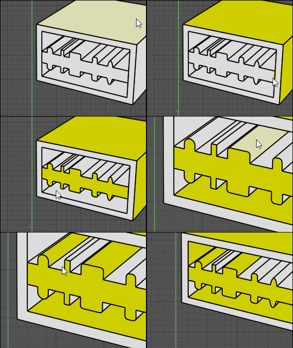
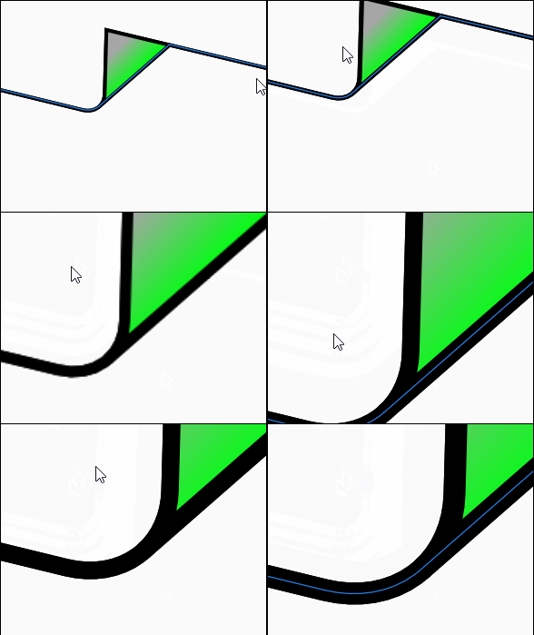
1) Outline that is stroked outside of path rather than along center of path. When outline stroke is outside then edges meet corners properly:

But, when the outline stroke is centered then edges don't meet correctly but look offset:

A stroke can only be outside if the path is closed since open paths don't have an inside or outside.
2) block shading:

3) Hatch fill to indicate a cross-section plane:

Image Attachments:
 block_shading.png
 hatch_fill.png
 outline_centered.png
 outline_outside.png
From: Frenchy Pilou (PILOU)
I don't know if you have read the last Process because my computer crashes during its writing :)
Seems you don't make the Boolean and don't erase the inclined lines...before the first Export PDF !
How do you deal with these lines when you colorize?
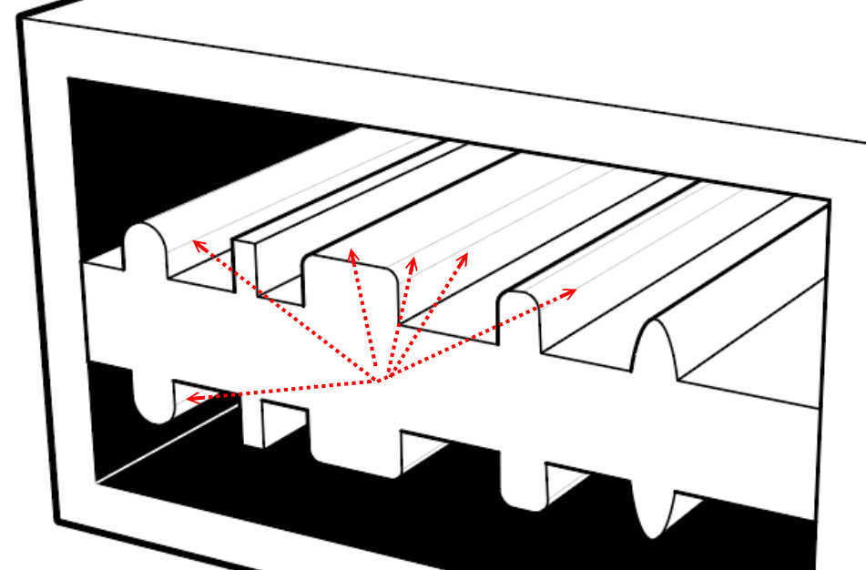
But ok for the no Boolean if you want the "frame"!
I make all inside MOI only from your file PDF!
About the width of the lines that will be made inside Affinity after the final export PDF from Moi...
But I am agree if the erasing of the no wanted lines was automatic that will be a breeze! :)
Else I have all surface that you want (so no Boolean at the start process;) from the Trimming intersection with the plane! ;)
Even before to have the closed curves! Even before the Explode Move who will permit the close curves process!
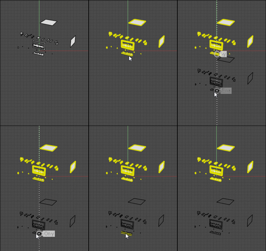
You must have something like this
For make the curves close : Join them! (before the Un ExplodeMove)
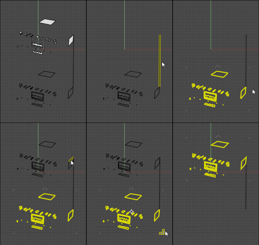
The Un-MoveExplode...twice 0.5 because ExplodeMove was 4
That is finished! All Closed Curves are in position ready for be exported in PDF (View Top) to Affinity V1
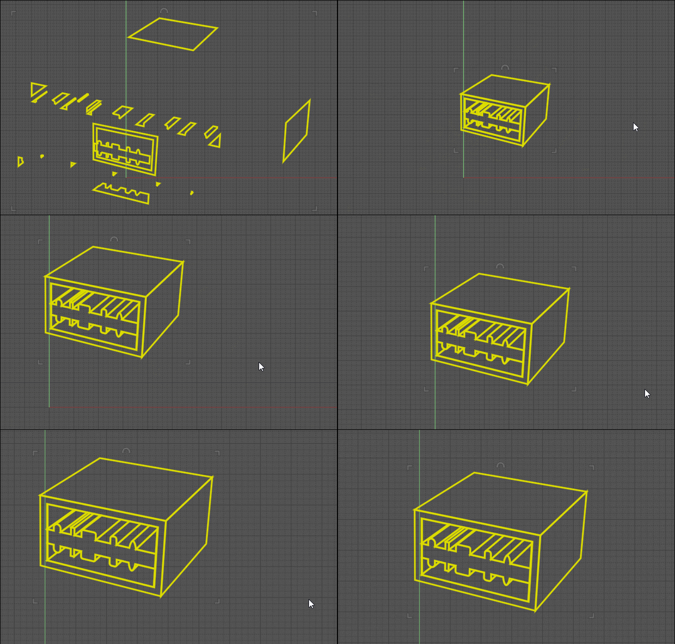
And inside Affinity V1 the round intersections seems perfect ! If not that is not a big deal to connect them in the right place!
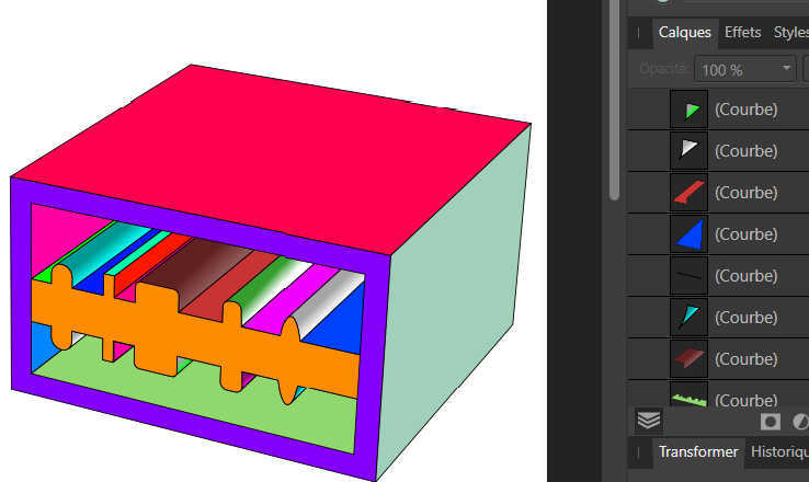
From: Frenchy Pilou (PILOU)
And of course the PDF ;)
https://moiscript.weebly.com/uploads/3/9/3/8/3938813/closed_paths_test_ok.pdf
From: pressure (PEER)
Wow Pilou! I'm impressed by your creativity. I got your method working by using Trim rather than Boolean > Intersection.
I'm going to experiment more with your method tomorrow :)
From: Frenchy Pilou (PILOU)
My last one was without Boolean! ;)
But maybe there is more easy ...maybe just an intersection with a tricky plane ?
The only default that i see is the Lines to erase "manually"!
Because on a very complex object that will be very painful or impossible! :)
From: Frenchy Pilou (PILOU)
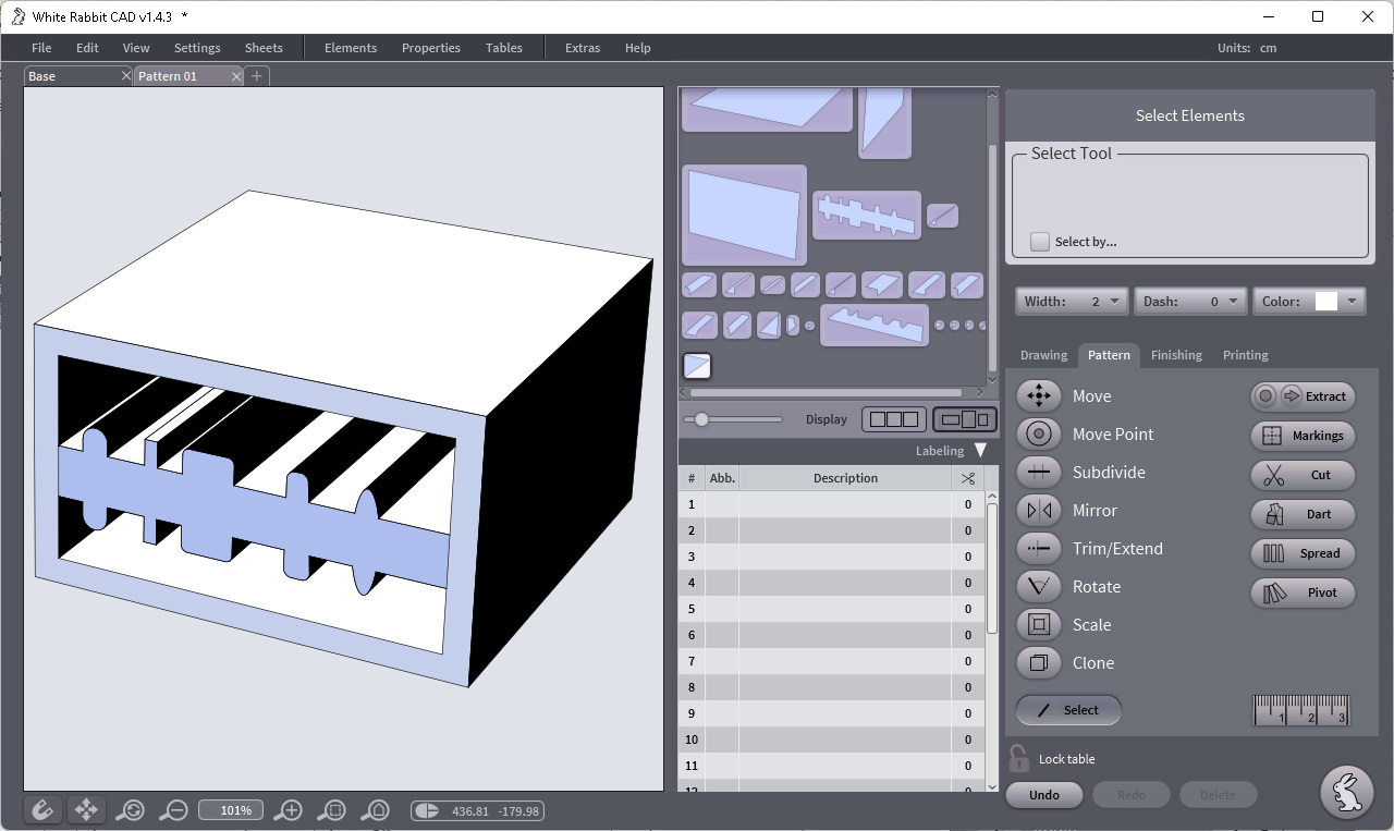
@ Peer The mystery of the SVG file is quasi resolved! :)
It was a "," who must be changed in "."
So by Taron the creator of White Rabbit CAD! ;)
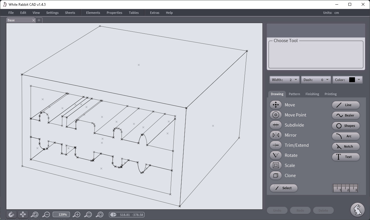

From: Frenchy Pilou (PILOU)
Here the secret! :)
As I can't load any file SVG inside the White Rabbit CAD
https://www.tiesoli.com/whiterabbitcad/
a 2D niche program for make clothes! :)
you must edit the svg file
Check the: viewBox="0 0 595,2756 841,8898"
Change it to be:
Check the: viewBox="0 0 595.2756 841.8898"
Now all works like a charm! :)
I don't know who is the guilty! :)
Inksape, Moi, White Rabbit Cad...
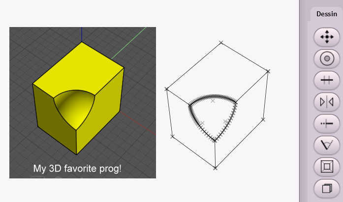
From: Michael Gibson
Hi Pilou,
re:
> I don't know who is the guilty! :)
> Inksape, Moi, White Rabbit Cad...
It's a bug in MoI's SVG export, it should not be using localized number formatting for those values in the SVG file, I'll get it fixed up.
Thanks, - Michael
From: Frenchy Pilou (PILOU)
Very cool...i can reload a Moi file SVG now if needing!
From: pressure (PEER)
Hi Pilou,
Thank you for putting so much time and thought into this problem!
I tried out your method of trimming a plane with curves from SVG. It turns out there are a couple problems when I do this with a more complicated drawing. The first is that hidden line generation leaves behind a bunch of tiny lines in the SVG. Normally these aren't visible, but they're enough to cause tiny little cuts in the plane which then prevent joining the edge curves into closed paths. I tried removing the hidden line fragments, but it takes a lot of manual work.
The second problem is that, even after removing all the hidden fragments, trimming a plane with a jumble of curves isn't totally reliable. Some cuts get missed and sometimes some bug gets triggered and I see a bunch of triangular artifacts rather than a properly trimmed plane.
White Rabbit CAD looks good. For this task I'm probably going to stick with Illustrator since I already know how to use it. But, next time I have a sewing project, I'm certainly going to try it. Please thank Taron for me :)
- Peer
From: Frenchy Pilou (PILOU)
in any case that tracked down a bug inside MOi ! ;)
White Rabbit is a very specialized program!
Its tools 2D are some ergonomic to use for draw curves or other geometric forms! :)
And smart UI like Moi! ;)
From: Rainydaylover (DIMITRI)
A cage deforming tool. It is the tool I am waiting to see in a coming version for buying the upgrade from v.3.
From: Psygorn (DRILLBIT)
Hi Michael,
I hope you are doing well.
I want to request a feature! ( I don't know if it is already exists or if it is asked by someone else and I hope it will not turn out to be dumb request)
Is it possible to be able to save MOI scene in different modes? I mean for example can one save MOI scene in different c-plane modes or if different Zooms? so, there would be c-plane-1, c-plane_2 etc. Zoom_1, Zoom_2. I think it could be useful if one could save MOI scene in different c-plans modes so s/he could quickly toggle between these modes and could see the model from different angles.
Best,
Psygorn
From: pressure (PEER)
Hi Psygorn,
Have you tried the ViewManager script?
http://moi3d.com/forum/lmessages.php?webtag=MOI&msg=10028.1
For saving c-planes it works pretty well to add an alignment feature like a little plane or 2 lines at right angles so that the orientation picker of the c-plane command can be snapped back to where it was.
- Peer
From: Psygorn (DRILLBIT)
Hi Peer,
I didn't know about it!
Thanks :-)
From: christian (CHRI)
hi Peer
Thanks for sharing this script
it works fine
christian
From: pressure (PEER)
Hi Michael,
Please add some functionality to Delete where if I select some naked edges and hit Delete then the surfaces get extended, intersected, trimmed, and joined. Like if I delete a fillet chain and then select all the naked edges left behind and hit Delete, I’ll get a sharp-edged surface/solid that’s all joined up. Or if I delete the faces of a pocket that's at the junction of a few faces (not necessarily an inner loop), select the naked edges, and hit Delete then the pocket basically gets filled in.
I think there might be some "remove face" or defeaturing stuff in ACIS.
- Peer
From: pressure (PEER)
Hi Michael,
Please add typographical points (1/72 of an inch) as a unit system. Right now it is cumbersome to deal with text and with lines that have width since both are generally defined in terms of points. This will also probably help with the output of make2d since that seems to be in points.
- Peer
From: Michael Gibson
Hi Peer, unfortunately typographic points are not commonly used as a unit system in CAD software. So adding that would trigger some compatibility issues around data transfer.
- Michael
Show messages:
1-4
…
445-464
465-484
485-504
505-524
525-544
545-564
565-584
…
645-656


![]() block_shading.png
block_shading.png
![]() hatch_fill.png
hatch_fill.png
![]() outline_centered.png
outline_centered.png
![]() outline_outside.png
outline_outside.png


