Show messages:
1-10
…
31-50
51-70
71-90
91-110
111-130
131-150
151-158
From: nameless
Michael,
This is stellar... I can't believe you made this happen so quickly. For me, asset placement is solved with the most elegant/intuitive way.
Thank you so much for keeping your eyes on MoI user needs and for helping us tirelessly. It's so inspiring!!!
From: Michael Gibson
Hi nameless, you're welcome! Through e-mail you asked if this could be used in the CustomUI object library. I think that should work ok, you would edit the file ObjLibrary.menu.htm on line #26:
code:
else { moi.command.execCommand( 'importpart '+file); }
Make that say importpartwithscale instead, but take care not to accidentally remove the space that is after it.
- Michael
From: nameless
Perfection!
From: Mik (MIKULAS)
Hi Michael,
thanks for more details regarding "4views" project.
re:
>So I mean more like this - you have your model you've made in one file, and a title block template set up in a separate file. Now go ahead and add in dimensions on your model. Then you export to PDF and there is an option for the view configuration. It would have options for "Top", "Front", "Right", "3D" (all single view drawings as it is now), "4 views", or "Use title block template".
If I understand it correctly I make dimensioning on model (part) in all required views in one file, let say in MOI Split view, which is similar to 4 view projection. That's fine.
Only two questions:
.: Would it be possible to "turn off" unusable/invisible dimensions in given view and in 3D view? I mean dimensions marked by white arrow.

.: Would it be possible to specify before export First-angle projection or Third-angle projection (
https://en.wikipedia.org/wiki/Multiview_projection)? I mean for example Top, Front, Right and 3D view in specific order given by ANSI or ISO standards, pls see bellow.

Thanks a lot.
Mik
Image Attachments:
 4viewsDIM.jpg
ANSI vs ISO technical drawing.jpg
4viewsDIM.jpg
ANSI vs ISO technical drawing.jpg
From: Mik (MIKULAS)
BTW:
ImportPartWithScale is very useful script, only as a reminder for me, that Import Icon has two different options, I've reworked ImportIcon.png and copied to c:\Program Files\MoI 4.0 beta Oct-27-2020\ui\icons\ImportIcon.png

Mik
Image Attachments:
ImportIcon.png
From: nameless
Mik, I wasn't even aware of the existence of this RMB mode of import button until I read your comment!
Image Attachments:
Untitled-1.jpg
From: Mik (MIKULAS)
I don't either :-D
MOI is so intuitive that it isn't necessary to read Command Reference :-)
Mik
From: Michael Gibson
Hi Mik,
re:
> If I understand it correctly I make dimensioning on model (part) in all required views in one file,
> let say in MOI Split view, which is similar to 4 view projection. That's fine.
Yes, that's the idea.
> .: Would it be possible to "turn off" unusable/invisible dimensions in given view and in
> 3D view? I mean dimensions marked by white arrow.
Yes, to make this work there would need to be a new property on dimensions. Something like:
Show in: "All views" , "Ortho views only" , "3D view only".
> .: Would it be possible to specify before export First-angle projection or Third-angle projection
> (
https://en.wikipedia.org/wiki/Multiview_projection)? I mean for example Top, Front, Right and
> 3D view in specific order given by ANSI or ISO standards, pls see bellow.
Yes, the idea is that you would be able to put any arrangement you want in the template file. In the template file you would put a rectangle where you want to have a view placed and give the rectangle an object name to identify the view to use. I was thinking the 3D view would use the view from the current 3D viewport but maybe there could also be a way to specify a particular view direction in the template object name as well.
- Michael
From: Mik (MIKULAS)
Hi Michael,
3xYes in answers... that sounds promising :-)
Seriously, it would be absolutelly perfect!
Thank you.
Mik
From: Mip (VINC)
Hi Michael,
> Yes, to make this work there would need to be a new property on dimensions. Something like:
> Show in: "All views" , "Ortho views only" , "3D view only".
Will the "Ortho views only" hide, for example, the "Front" dimensions to appear as lines in the "Top" view ?
I mean just like the "thickness" of "Images" placed in the "Front" view are invisible in "Top view".
Would there be a "View" property of a Dimension that makes it belong to a view ?
Actually, I find Make2D Script quite useful because it makes it very easy to add measurements to the Ortho views.
Would it be interesting to have that script included in the dimensions Pane ?
The only thing I would like to be added to it would be to act like placing an Image
(I mean letting the user choose (click) where the 2D should appear in the 3D space).
Thanks for the hard work !
Looking forward to the final v4 version.
Michel
From: Mip (VINC)
Hi Michael,
Here are some observations on v4 beta:
Copy as PDF :
When "Exporting as PDF", the objects sizes are preserved while when "Copying as PDF" they aren't.
edited :
(could be a problem with the way Affinity Photo and Affinity Designer read the PDF.
If I "Place" a previously exported PDF file into the Designer document and double
click it, it opens an "integrated window" and if I then "Paste" a copy PDF from MoI in it, the size is ok).
Copy and Export as PDF
Tick marks have the thickness of drawing lines instead of being the size of dimension lines.
Small display error when drawing solids (not specific to v4. It is really minor as the result is not affected) :
Draw a solid cube, lets say 10 x 10 x 10, starting at Origin, then, in the 3D view, start drawing another solid (or a rectangle) right "underneath" the first one, again starting at Origin. When you move the mouse to the back of the plane, it will display a negative value as long as the cursor is moved under the measurement of the bottom of the solid on top.
It doesn't cause any error if you click to fix the point. It is just indicating a minus sign in a positive area while moving the cursor.
Dimensions wish :
Would it be possible to add the Style (color) property to the Defaults as it already appears in Details?
Extrude command wish :
Not exiting the command after specifying extrusion length (would wait for right click by user).
It is similar to an earlier demand by Leonardo, but more specific to the use of options within the command.
Specially if Tapered is activated, if one enters the Extrusion Distance then press Tab, the cursor won't go to the Draft Angle text box.
If Tab is pressed, it would be possible to go back and forth Extrusion/Draft angle and only end the command on right click.
Add an Axis Show/Hide check box in the "Grid Snap" button wish :
This check box would be under the Show Grid checkbox.
Thanks again,
Michel
Image Attachments:
Rectangle creation under solid.png
From: Michael Gibson
Hi Michel,
re:
> Will the "Ortho views only" hide, for example, the "Front" dimensions to appear as lines in the "Top" view ?
> I mean just like the "thickness" of "Images" placed in the "Front" view are invisible in "Top view".
I was thinking "Ortho views only" would have the same behavior as current ortho views. But there could be additional settings to limit it to just one ortho view. Maybe:
Show in: "All views", "Ortho views only", "3D view only", "Top view only", "Front view only", "Right view only".
> Would there be a "View" property of a Dimension that makes it belong to a view ?
Yes this would be a setting for a dimension to be displayed only in certain views so you could control generating a multi-view PDF file better.
> Would it be interesting to have that script included in the dimensions Pane ?
Yes that seems like it would be good.
> The only thing I would like to be added to it would be to act like placing an Image
> (I mean letting the user choose (click) where the 2D should appear in the 3D space).
They are selected when the command ends so you can position them using Transform > Move or dragging them. Maybe there could be an option to generate it inside a rectangle with a specific object name similar to how a title block template could work.
- Michael
From: Michael Gibson
Hi Michel, thanks for the feedback.
re:
> Copy as PDF :
> When "Exporting as PDF", the objects sizes are preserved while when "Copying as PDF" they aren't.
> edited :
> (could be a problem with the way Affinity Photo and Affinity Designer read the PDF.
> If I "Place" a previously exported PDF file into the Designer document and double
> click it, it opens an "integrated window" and if I then "Paste" a copy PDF from MoI in it, the size is ok).
I'm not able to repeat this with Adobe Illustrator, it appears to be a quirk in how Affinity handles pasting. It appears to be sensitive to the DPI setting in Affinity. Affinity seems to think the PDF file is 72 dpi (I don't think there is actually any kind of dpi setting for a whole page in PDF), and if your current Affinity document has a different dpi then it scales it.
Before you paste into Affinity, if you go to Document Setup > Dimensions and set DPI = 72 then it seems that it will paste it over without altering the size.
Pasting into a "Placed" PDF file works I think because the placed PDF file has DPI = 72.
re:
> Copy and Export as PDF
> Tick marks have the thickness of drawing lines instead of being the size of dimension lines.
Tick marks have their own line thickness setting which is used. It's set in the Annotation properties > "Arrows" section, "Tick line width".
You can alter it for an individual object using Details... or set the default for a newly created one under Options > Dimensions.
> Small display error when drawing solids (not specific to v4. It is really minor as the result is not affected) :
> (width shows as negative)
It's actually not an error - it's due to the drawing using the faces of the cube as the current snap plane when you are placing points in the 3D view and have snapped points onto an object. If you turn off object snap or hold down Alt to temporarily turn off object snap for that pick so you don't have both points snapped onto the plane then it won't use the solid cube's plane as the current cplane orientation.
This is what allows for drawing things like rectangles directly onto the face of a box when you are picking points in the 3D view.
> Dimensions wish :
> Would it be possible to add the Style (color) property to the Defaults as it already appears in Details?
Hmmm, well currently when you draw any object it gets the "active style" applied to it, that is the one that has a ring around its color swatch in the Styles list in the Scene browser. You can set it by right clicking on a swatch. That is how the style assignment for new objects works for all object types including dimensions. But if I understand you correctly you want a way to set a default style for a dimension in the dimension preset instead of having it use the active style?
> Extrude command wish :
> Not exiting the command after specifying extrusion length (would wait for right click by user).
I don't know, this may be too big of a change. Having an extra step for all uses of Extrude is kind of like paying a "workflow tax" on all simple extrusions just to make that back and forth between Draft angle and distance work for the tapered case.
> Add an Axis Show/Hide check box in the "Grid Snap" button wish :
> This check box would be under the Show Grid checkbox.
If you want to put this in now, you can do it by editing the file GridSnapMenu.htm inside the ui folder.
Add this below the <moi:CheckButton> for "Show Grid" on line #19 :
code:
<moi:CheckButton binding="value = moi.grid.showXYAxes"><moi:Text textid="Show grid axes checkbox"/></moi:CheckButton>
- Michael
From: christian (CHRI)
Hi Michael
Thanks for all these improvements
i m using Dim without changing "aux" plans
the next file is a animed gif
do you think that i use it like i should ?
Chri
Image Attachments:
TEST.3D.gif
From: Frenchy Pilou (PILOU)
Seems you don't use as you should! ;)
an hypothenuse diagonal is bigger than a side...etc
else the rest is tricky! ;)
Inclined vertical or horizontal selection is cool : only one point to move after for have same length of dimension!
From: Frenchy Pilou (PILOU)
In 3D View seems the rule is not to click on vertex but on edges for better position dimensions wanted !
and move points after if needing!
From: Michael Gibson
Hi Chri,
re:
> do you think that i use it like i should ?
I guess so - is there a particular result that you are not able to get?
One thing to note is that when you are drawing in the 3D view, the view direction plays a role in what plane will get used. It will be the one that is closest to facing you.
Here's an example - here I'm doing the same Dim Horizontal drawing command on the same points, but adjusting the view between uses to target different planes:
- Michael
From: Frenchy Pilou (PILOU)
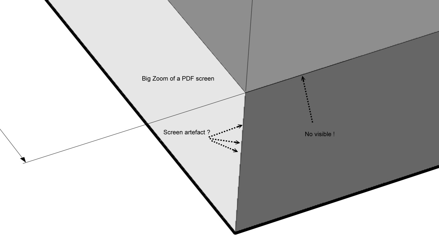
"Plane" is depending of the rotation of the 3D view ?
Trick of the inclined selection avoid to rotate the view but there is no equal length of side lines...
I suppose that is not visible if lines are same color than volume for print ?
Indeed (but i have not Printed for see if "artefact" are visible or not!
From: Michael Gibson
Hi Pilou,
re:
> Trick of the inclined selection avoid to rotate the view but there is no equal length of side lines...
> I suppose that is not visible if lines are same color than volume for print ?
Sorry I don't understand this part.
- Michael
From: Michael Gibson
Hi Pilou,
> Trick of the inclined selection avoid to rotate the view
Rotating the view is how you control it, so it doesn't make sense to avoid rotating the view.
> "Plane" is depending of the rotation of the 3D view ?
Yes, it's the same as drawing other planar shapes. For example the plane that a circle will use is controlled in the same way and has been for a long time:
Hope this helps!
- Michael
Show messages:
1-10
…
31-50
51-70
71-90
91-110
111-130
131-150
151-158