Show messages:
1-15
16-35
36-55
56-75
76-95
96-115
…
156-158
From: Mik (MIKULAS)
Hi Michael,
pls find attached PDF export examples.
It works perfectly!
Dim Test.pdf was exported via your excellent Make2D4Views script, Dim Test2 was exported from copied models and arranged into same views as via script.
When I exported Dim Test.pdf the dialog window didn't offer Line styl option as in case of export directy from arranged 3D models.
It woud be great to have Line style option for export lines only or new script "ArrangeModelInto4Views" :-)
Is it possible to avoid the "corner line" in angular dim?

Mik
Attachments:
 Dim Test 2.pdf
 Dim Test.pdf
Image Attachments:
 Angular Dim Corner.jpg
From: Mik (MIKULAS)
Probably new script "ArrangeModelInto4Views" woud be more useful for possibility of shaded backround.
Mik
Attachments:
 Dim Test 3.pdf
From: Mik (MIKULAS)
Hi Michael,
I have one more question.
If I export some geometry and uncheck before export "generate hidden lines", then dialog window appears "Generating hidden lines" and some time it takes generating hiddens lines probably, but they are invisible in exported geometry.
No problem with simple model, but it takes significant amount of time when it's exported complex model.
Is it such behavior correct?
Thanks
Mik
From: Frenchy Pilou (PILOU)
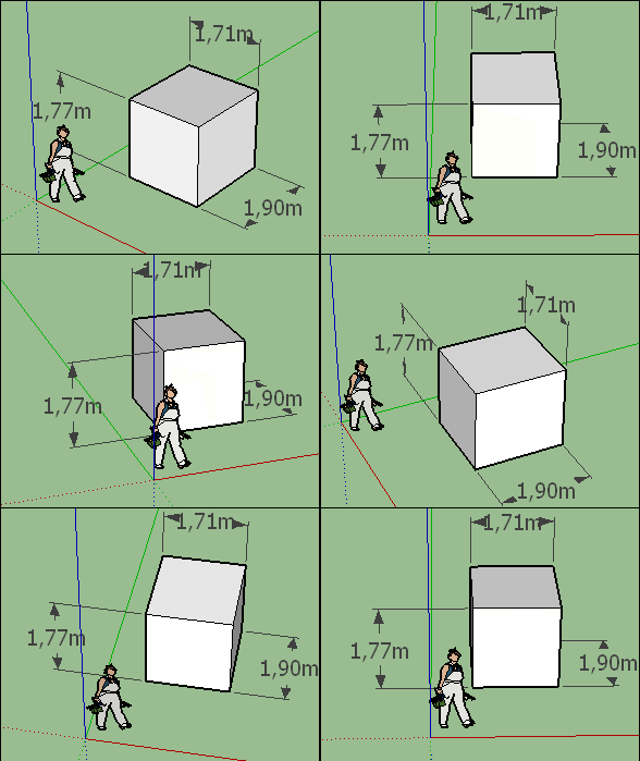
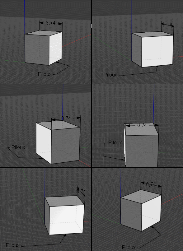
Does it possible to have Dimensions "Front Camera" in the 3D View?
Like here in SketchUp

From: Mik (MIKULAS)
Hi Pilou,
I think that yes, after clicking on the annotation details it has to be chosen in Annotation properties/Display/Screen aligned.
Mik
From: Michael Gibson
Hi Pilou, yup like Mik writes above that's available with this setting:


If you want to set it on an individual dimension you can do that by selecting it and using the "Details..." button to get to the Object properties dialog shown above.
If you want it to be the default behavior for newly drawn ones then set it in the preset properties under Options > Dimensions.
- Michael
Image Attachments:
 pilou_screen_aligned1.jpg
 pilou_screen_aligned2.jpg
From: Frenchy Pilou (PILOU)
Indeed! Excellent!

From: Michael Gibson
Hi Larry,
re:
> Well in that case, I'd vote for keeping it simple now to ease your future plans. Since I'm
> just an amateur draftsman, probably worth waiting to see what the professionals think
> regarding the need for an "Arrow gap".
Well these functions are intended for use by "amateurs" too! :)
The Arrow gap functionality is in there now actually, you should be able to use it with those scripts.
I think I may have come up with a good idea for how it can co-exist with a spline curve leader without too much trouble.
> Attached. While Max's script has been greatly appreciated, your new dimensions tools are a treat
> to work with and I really like being able to see the Text and Value fields in this new beta. In this
> case some simple plans for an addition.
These are great, thanks for sharing them!
Was this using the "Scaling: By screen size" method?
- Michael
From: Larry Fahnoe (FAHNOE)
I'll experiment with the Arrow gaps coming up!
Yes, I'm using the "Scaling: By screen size" method.
--Larry
From: stefano (LIGHTWAVE)
Hi Michael, thanks for all your help and improvements! Cheers Stefano
From: Michael Gibson
Hi Mik,
re:
> pls find attached PDF export examples.
Those are looking really good!
> When I exported Dim Test.pdf the dialog window didn't offer Line styl option as in
> case of export directy from arranged 3D models.
The line style options only show up when you have some solids or surfaces being exported so it's doing a hidden-line drawing generation.
I have it on my "after v4" list to have some controls for line width on the wireframe type export as well.
> It woud be great to have Line style option for export lines only or new
> script "ArrangeModelInto4Views" :-)
I'd like to get it set up so you could generate 4 views as a built in part of the exporter.
> Is it possible to avoid the "corner line" in angular dim?
Hmm, no not currently. I guess that's why other CAD program use small lines around the arrowheads rather having the lines connect to the center point.
I'll take a look at cleaning that up.
Thanks, - Michael
From: WN
Hi Michael.
> Can you please describe this one a bit more? If you could also post the .3dm model file that may help me understand.
I meant this:
https://yadi.sk/i/hOZXJfOYyTzAVA
Without all this, of course, you can do, and what you have done will cover most of the tasks.
I can't imagine how difficult it was for you but judging by the time spent it was a rough trip with a big backpack and a bunch of boy scouts. :)
With the successful completion of the journey!
Attachments:
 dim_2.pdf
From: fcwilt
Hi,
A minor issue.
When exporting the 3DM file being exported from is marked as CHANGED.
If there is no change that I need to save could it be NOT marked as changed?
Thanks.
Frederick
From: bemfarmer
The symbol Ø refers to the Diameter of a circle, or a circular arc.
R is for radius.
https://www.designtechacademy.com/2017/09/3-gd-symbols-diameter-radius-controlled.html
I see CR, SR, and SØ Could be used with a Leader.
I never took a drafting class. Is there a good, simple website for the basics?
- Brian
alt 0216 = Ø
(use numeric keypad)
From: Mik (MIKULAS)
Hi Michael,
re:
> Hmm, no not currently. I guess that's why other CAD program use small lines around the arrowheads rather having the lines connect to the center point.
It would be great, because then we can avoid this:

... only from interest: Would it be possible to add somewhere to Annotation properties somewhat like Scale factor, which recalculates dim values according specific Scale?

I know, I can write dirrectly the dim value in Text field, but it would be cool to have such feature :-)
re:
> I'd like to get it set up so you could generate 4 views as a built in part of the exporter.
What is your idea?
Sorry for too many questions: Did you have a chance to have a look on this post
http://moi3d.com/forum/index.php?webtag=MOI&msg=10011.38 regarding generating hidden line during export?
Thanks.
Mik
Image Attachments:
 Dim Test 6.jpg
 Dim Test Angular Spike.jpg
From: Michael Gibson
Hi Mik,
re:
> I have one more question.
>
> If I export some geometry and uncheck before export "generate hidden lines", then dialog window appears
> "Generating hidden lines" and some time it takes generating hiddens lines probably, but they are invisible
> in exported geometry.
The message "Generating hidden lines" with the progress bar means something more like "Generating a hidden line drawing", that means the whole process of calculating which pieces of curves are visible and which are hidden.
Then there are different types of curves that can be generated in the drawing - visible lines, outlines, silhouettes, and hidden lines. The outlines, silhouettes, and hidden lines can be turned off if you don't want those particular things. For some drawing types it can be good to show the curve pieces that are hidden in something faint like a dashed line style.
But even if you turn off the "Generate hidden lines" checkbox, the prompt with the progress bar will still say "Generating hidden lines", but there it's referring to the whole process really. That's just because that type of drawing can often be described as a "hidden line drawing" or "hidden line removal":
https://en.wikipedia.org/wiki/Hidden-line_removal. Does that make sense?
re:
> No problem with simple model, but it takes significant amount of time when it's exported complex model.
Do you have the "Canvas megapixel resolution" set to a high value possibly?
- Michael
From: Michael Gibson
@Larry:
re:
> Yes, I'm using the "Scaling: By screen size" method.
This method is not common in CAD but it is very convenient for simple drawings because you don't have to mess with setting scale factors to get a reasonable text size. With this method if you set it to have 12pt text, you see 12pt text on screen and it makes 12pt text in the PDF too. No giant text or tiny text.
- Michael
From: Michael Gibson
Hi WN,
re:
> I meant this:
https://yadi.sk/i/hOZXJfOYyTzAVA
Ok, that helps me understand now. Yes, I'll look at fixing that up.
If I understand correctly, you can use a workaround currently to get the result you want. The workaround is to initially place the radial dimension inside the arc's center point, then turn on edit points for the dim and drag the text point out like this:
But yes, it would be good to be able to draw one like that directly, I'll take a look.
- Michael
From: Michael Gibson
Hi Frederick,
re:
> A minor issue.
>
> When exporting the 3DM file being exported from is marked as CHANGED.
>
> If there is no change that I need to save could it be NOT marked as changed?
What file format are you exporting to where you are running into this?
It used to happen when exporting to a polygon mesh format, but that should actually be fixed in this beta release. I happened to skip including it in the release notes.
- Michael
From: Michael Gibson
Hi Brian,
re:
> I never took a drafting class. Is there a good, simple website for the basics?
Well it can be a little different between different industries.
Here's a cool overview for mechanical engineering that OSTexo posted a while ago:
https://ocw.mit.edu/courses/mechanical-engineering/2-007-design-and-manufacturing-i-spring-2009/related-resources/drawing_and_sketching/
- Michael
Show messages:
1-15
16-35
36-55
56-75
76-95
96-115
…
156-158

![]() Dim Test 2.pdf
Dim Test 2.pdf![]() Dim Test.pdf
Dim Test.pdf![]() Angular Dim Corner.jpg
Angular Dim Corner.jpg
![]() Dim Test 3.pdf
Dim Test 3.pdf


![]() pilou_screen_aligned1.jpg
pilou_screen_aligned1.jpg
![]() pilou_screen_aligned2.jpg
pilou_screen_aligned2.jpg

![]() dim_2.pdf
dim_2.pdf

![]() Dim Test 6.jpg
Dim Test 6.jpg
![]() Dim Test Angular Spike.jpg
Dim Test Angular Spike.jpg