Well it's been a while since my last tutorial and all I needed was a little time and some inspiration...
In the recesses of my mind lies a mental list of everyday household objects I would like to someday model in Moi3D.
A few decades ago, the everyday plastic stacking school chair was one of those objects kids, like myself then, were pretty much relegated to pondering (design-wise)... it was there everyday and you, plus all your friends had to sit in them.
But you say: "it's such a mundane and ubiquitous piece of cheap furniture... it's not like it's a
Marc Held or
Herman Miller Aeron chair worthy of gallery parties and exhibitions."
No, it's a
VIRCO.
Something must be great about this chair's design!
For starters: VIRCO MFG Corporation (
www.virco.com) has produced literally millions of the
"9000 Series" for use in thousands and thousands of school systems, churches and civic gathering centers all over the world for decades. It's extremely durable, easy to repair and many of them can be stacked vertically to save precious classroom space.
At just a few components, the chair consists of a polypropylene moulded plastic shell and a steel tube frame that is spot-welded and reinforced. Simple.
True masterpieces of industrial design are those that endure the test of time, and for one of two reasons: 1) They're well designed or 2) Well marketed. So maybe both.
I will show here how a plastic stacking school chair can be modeled in Moi3D.
When I started this tutorial, I didn't even know who manufactured these types of chairs, I was simply going from memory.
With that, I'll not be using any real-world measurements or proportions and will not be building this model with manufacturing techniques in mind.
This model is not an exact reproduction of the VIRCO chair, just a fun exercise.
But with my tutorial, hopefully you should be able to better realize some of the useful tools and methods available in Moi3D.
You should be able to apply some of the techniques to different designs and looks.
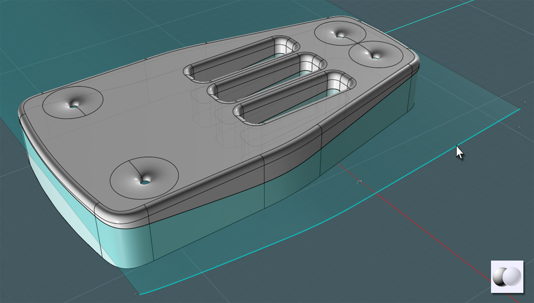
Here's the chair:
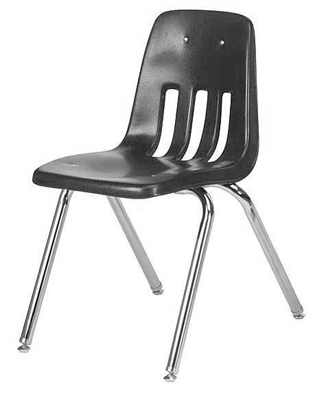
I spent a week or two actually trying different techniques to attempt the form of the plastic shell.
Myself, the master of Networks and Blends ran into a little difficulty.
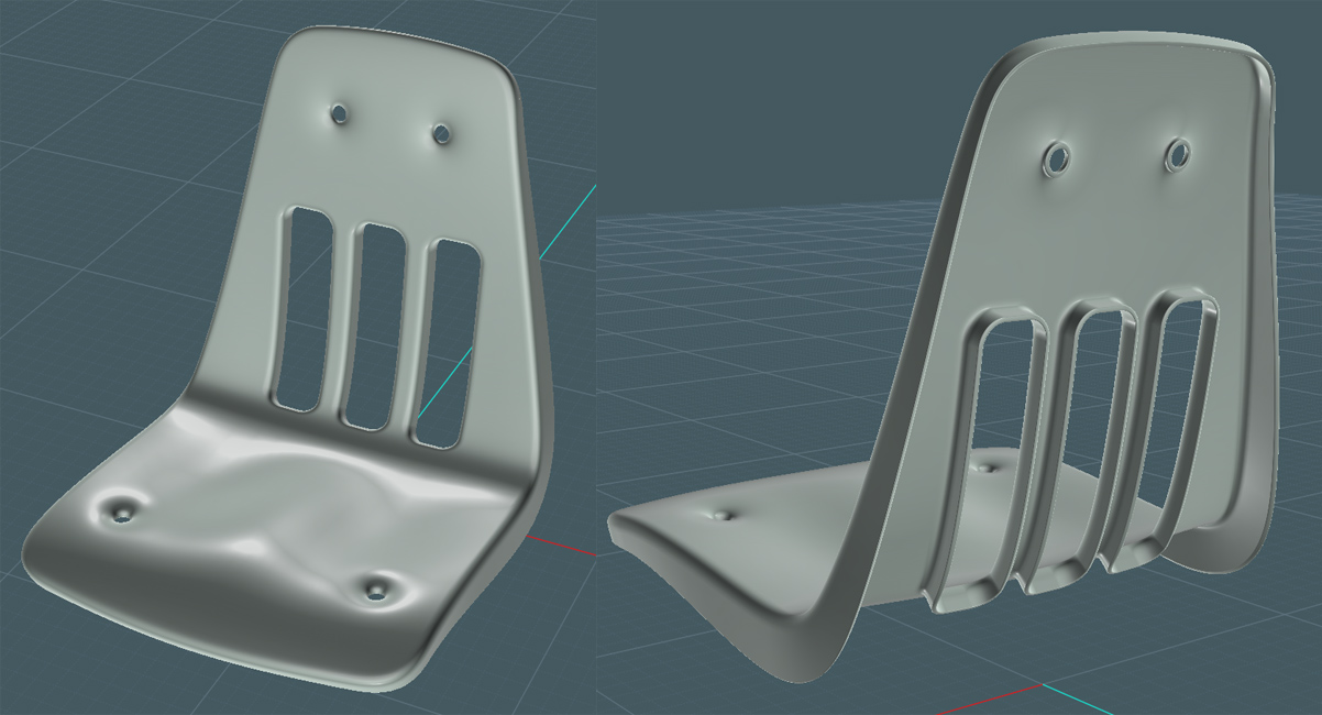
Though, deceptively simple, the shell is actually a complex shape!
Not only is there a lip of varying depth that runs around the perimeter, but there's a contour and subtle curvature to the seat and back.
Plus, there are these back vent holes and I also wanted to simulate the warping of the plastic near the large rivet holes.
Let's make this shell with a two-step processes; a "mechanical" and "organic". This way, we can better manage the result.
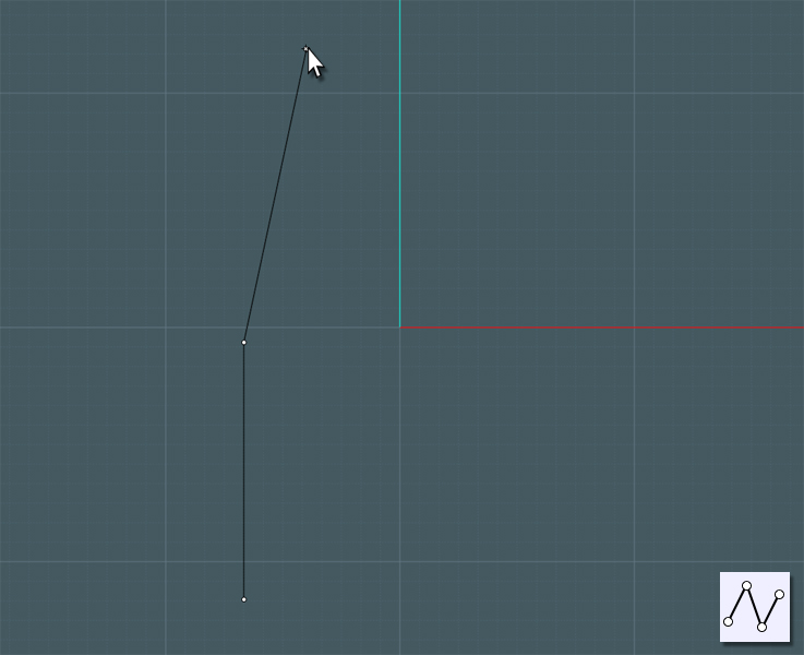
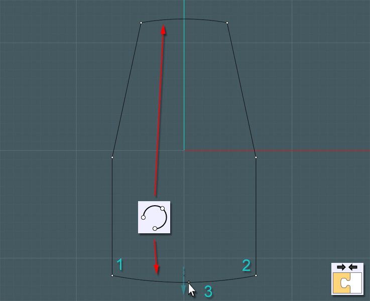
If you imagine the shell flattened out from it's "L" shape, you can use a few Polylines or curves to define the sides.
The middle C-plane line, half way up can represent the area just below the lumbar.
You can do everything on one side and then mirror a copy if you like, but sometimes it's easier to just to build both sides.
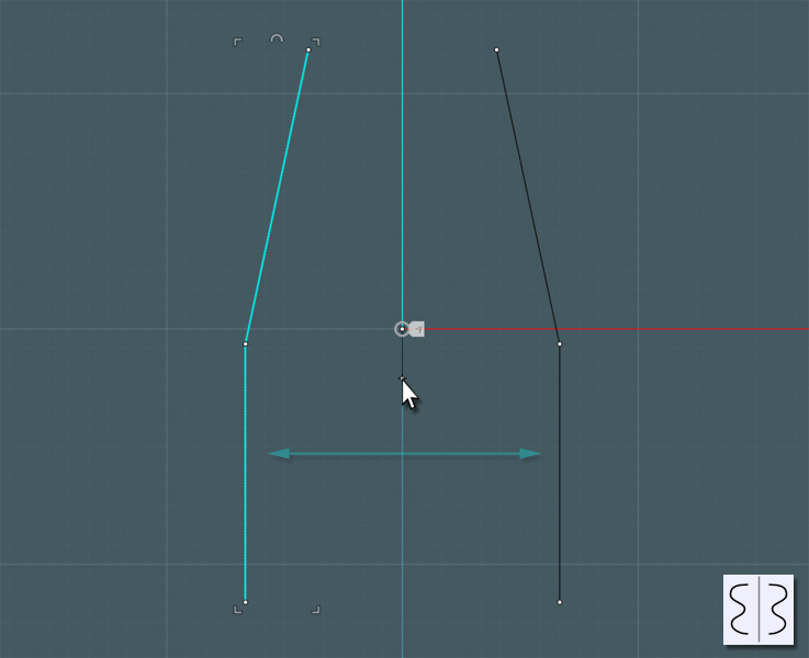
Well build in some 3-point arcs to complete the shape. The bottom arc is for the edge of the chair under the knee-bend, and so forth.
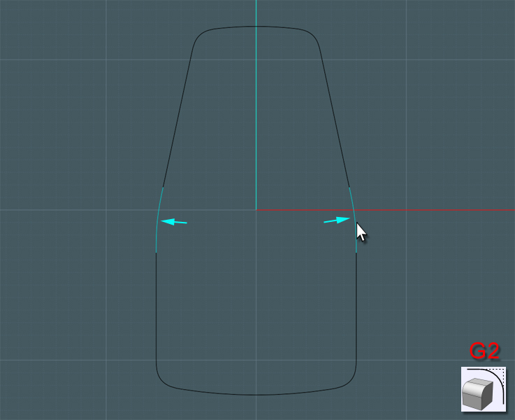
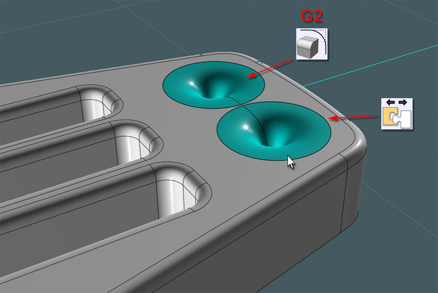
A "G2" Fillet of the corners will give the body a nice form.
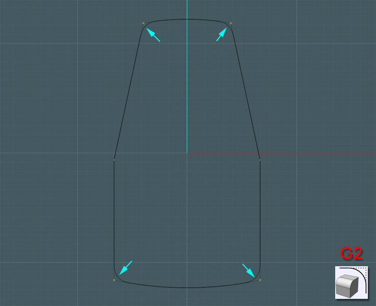
Larger fillets can be used to give a sweeping shape to the angle change on the sides.
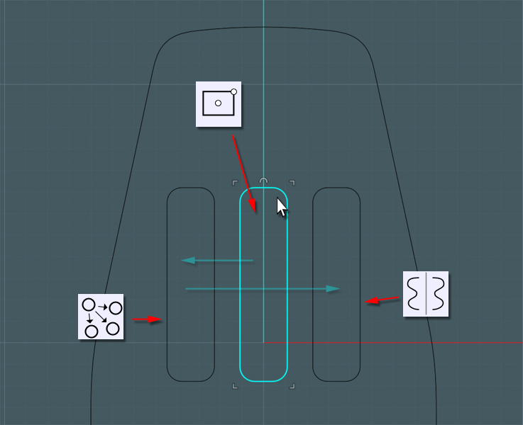
Now it's time to make the 'vent' holes for the back of the shell. This is really not a necessary feature from an engineering standpoint,
except that it does add an amount of stress-support with the structural 'ribs' acting as the sides of the openings.
Each company uses it's own pattern, whether it be circles, triangles or squares, and the particular design is a patented and copyrighted feature of their product.
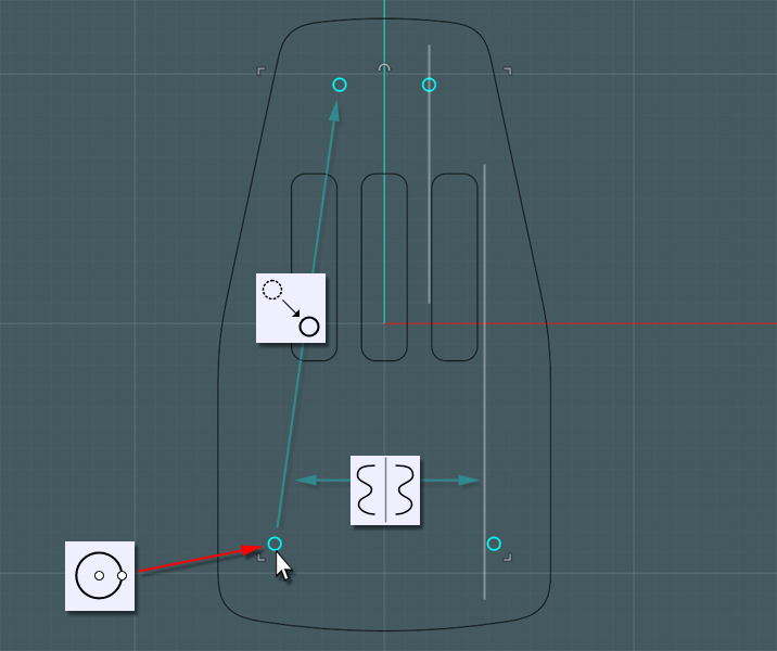
Inspired by the Virco model, we'll arrange three rectangles with rounded corners and place the bottoms of the shapes a little below the center line.
Lets make some small circle to represent the holes for the connecting rivets.
Place the two up top to tie in a support bar. The two bottom ones on the seat should be placed so that the frame tubes tied to them can run freely around the back vents.
Just select everything, provided it all lies within the same plane, and Extrude your shapes into one monolithic solid.
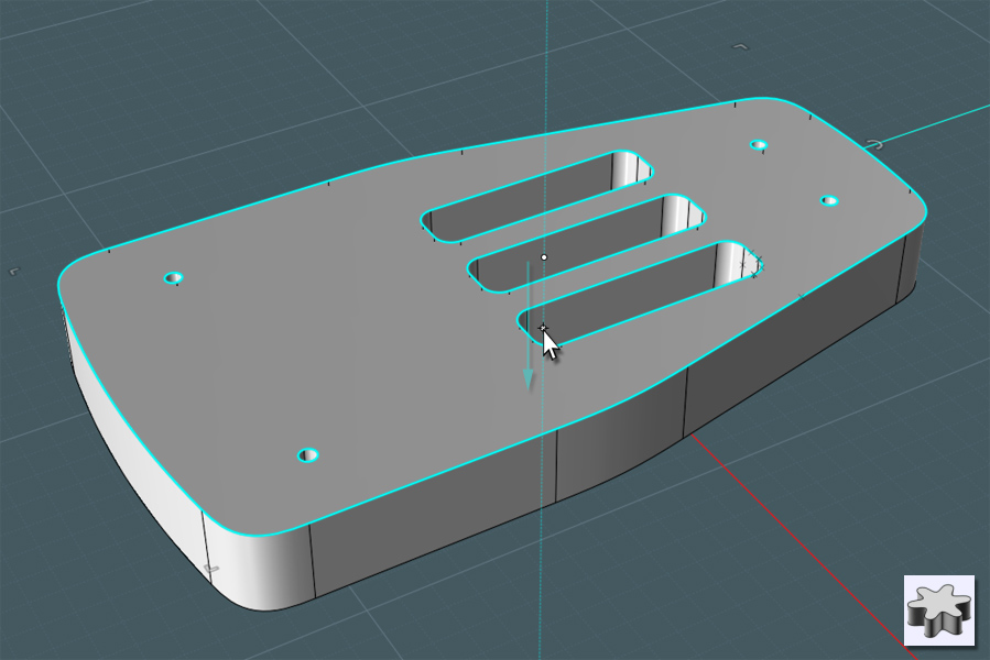
Fillet the solid.
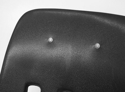
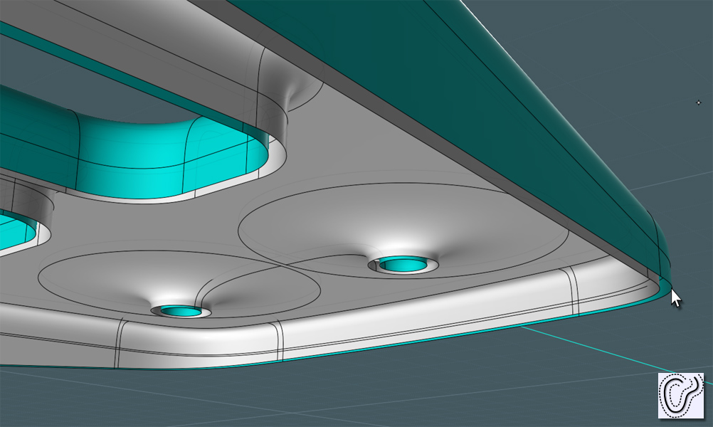
We're now going to simulate the dimples made by the compression of the rivets through the shell to the frame.
I used the largest Fillet allowed in this instance.
As shown here:
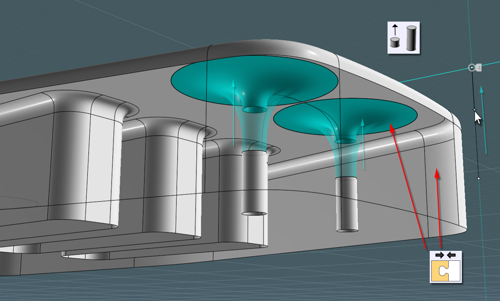
Now, unless the shell plastic is really thick, we'll need to compress the (Z) depth of the Fillet surfaces.
Separate them from the main object and use Scale 1-D to squish them upwards.
Join them back to the main body compound object once done.
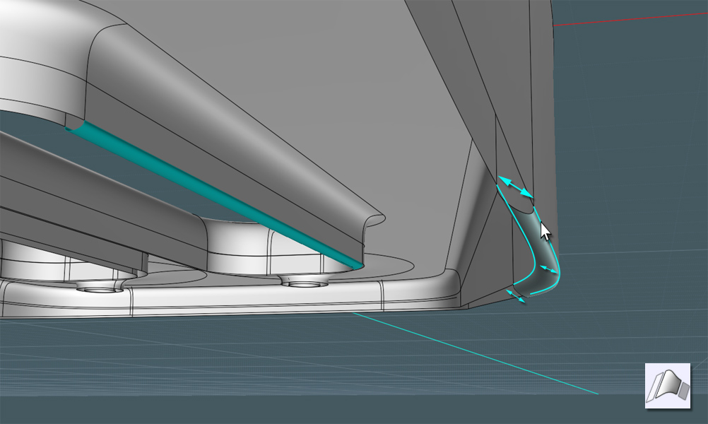
If you notice from the example diagram shown, the thickness, or depth, of the edge lip varies depending on where it is along the body.
Simply make a curve to represent the profile. Keep in mind to carefully place the deepest part where, once bent into form, will cause this area to be where you want it. Don't be afraid to go back 'to the drawing board'.

A Boolean Difference can be done to form the edge profile.
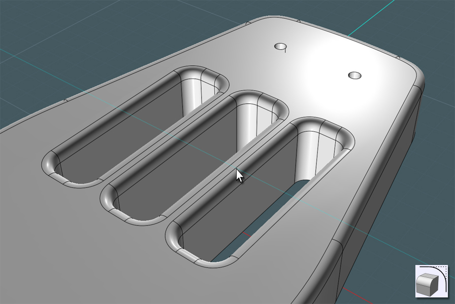
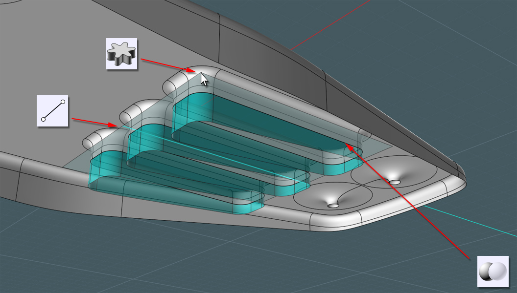
Use some skill :-) and trim the inside vent parts a little more recessed than the main edge lip.
I'm not going to mince words here... The NURBS Library may fail you here:
It's time to the Shell tool or Offset the remaining joined-surface set to give the part some perceived thickness.
It worked sometimes in my experimentation and not in other instances. Just do the best you can.
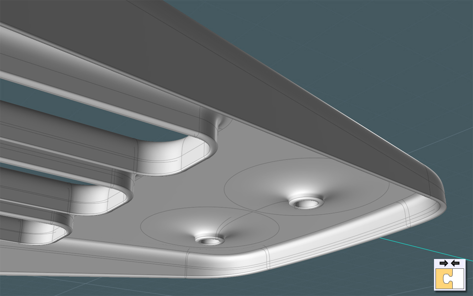
Here, I use a little personal touch; since I used the Shell command to make an adjacent surface, I Blend the edges together to make a nice round-over.
As you can see here, I 1-D Scaled in the inner surface so that it gave me a nice angled bevel. Though you don't have to use this step.
I just join the inner and outer surfaces, plus the blends, and it looks nice.
Now we should be done with the "mechanical" portion of the chair-shell form.
We were able to produce everything on a flat and manageable form that allows us to go back and make alterations if need be.
This would be very difficult on a more complex Network type form.
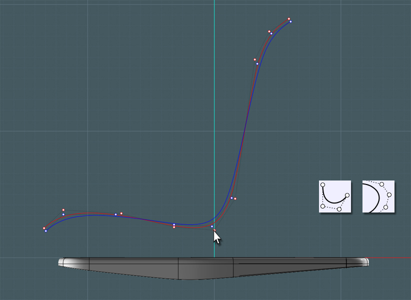
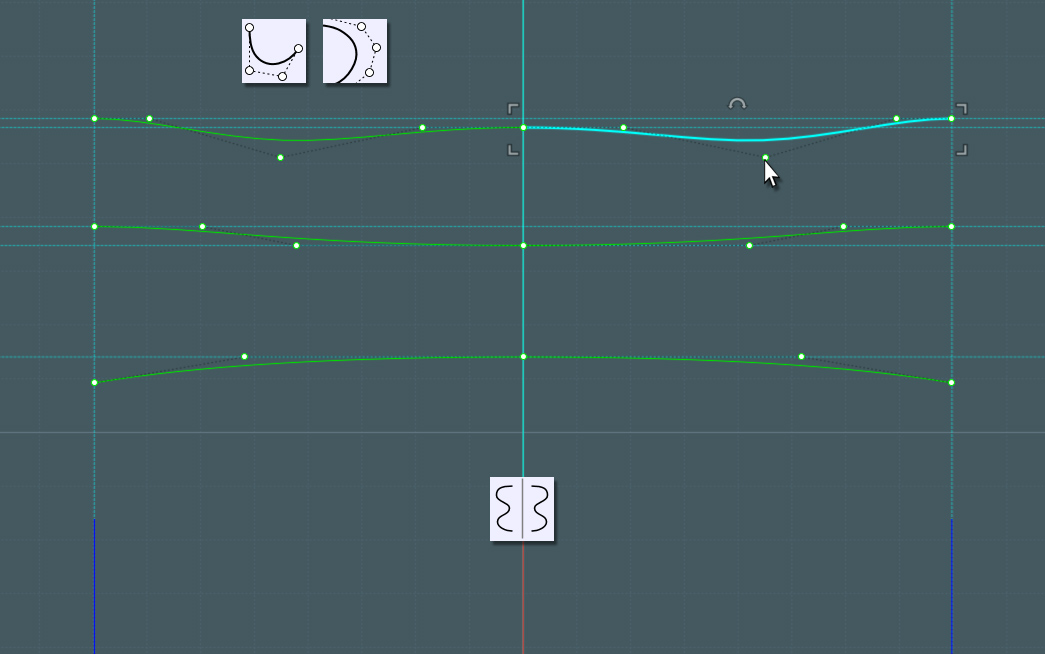
We'll need to build some profiles to represent the basic form of the seat and back itself.
In this example the red curve represents what I want the middle of the chair to do. The blue curves will be the sides.
Next: without regard to literal placement, I'll need to create several symmetrical profiles to represent 'what' the chair form is doing at different stages as you move from the knee-area to the upper back.
It is important to make sure that if you create a mirrored profile that the connecting points are 'tangent'.
Use the Orient tool to organize these profiles in their appropriate positions. Go to your side views and adjust where necessary.
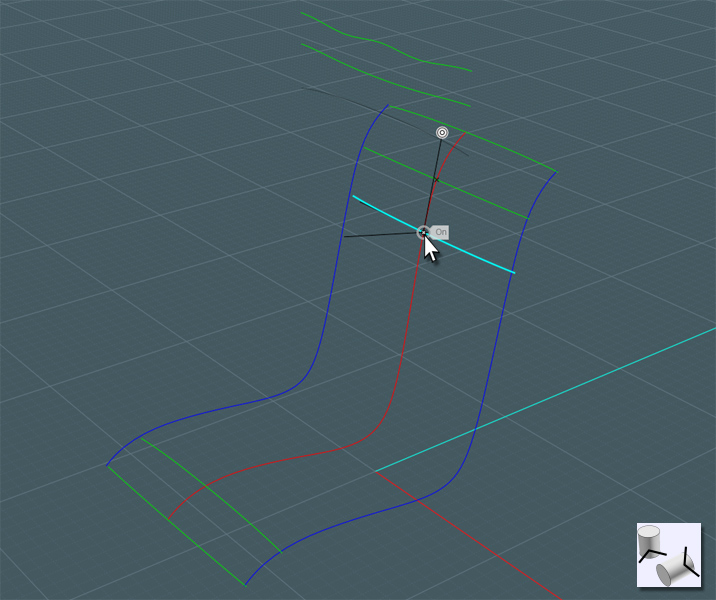
Now make a Network surface from your profile matrix. Please note that the end points of the inside profiles should actually touch along the outer profiles. Network will often have issue if not set up tight enough.
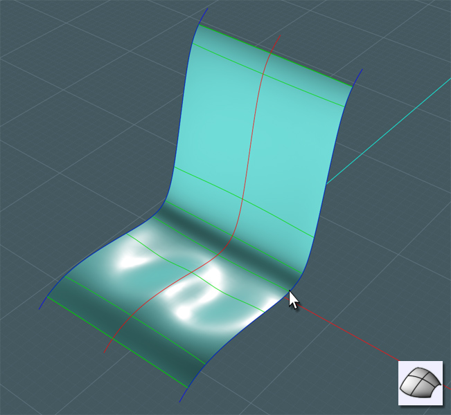
You'll now have a form to represent the "organic" part of the shell form.
[You'll need Moi V3 from here on out]
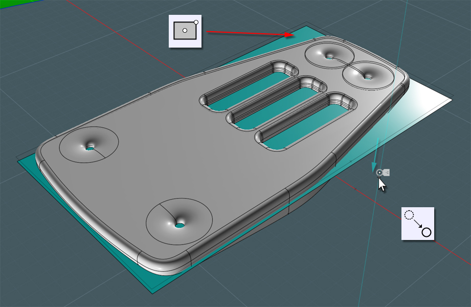
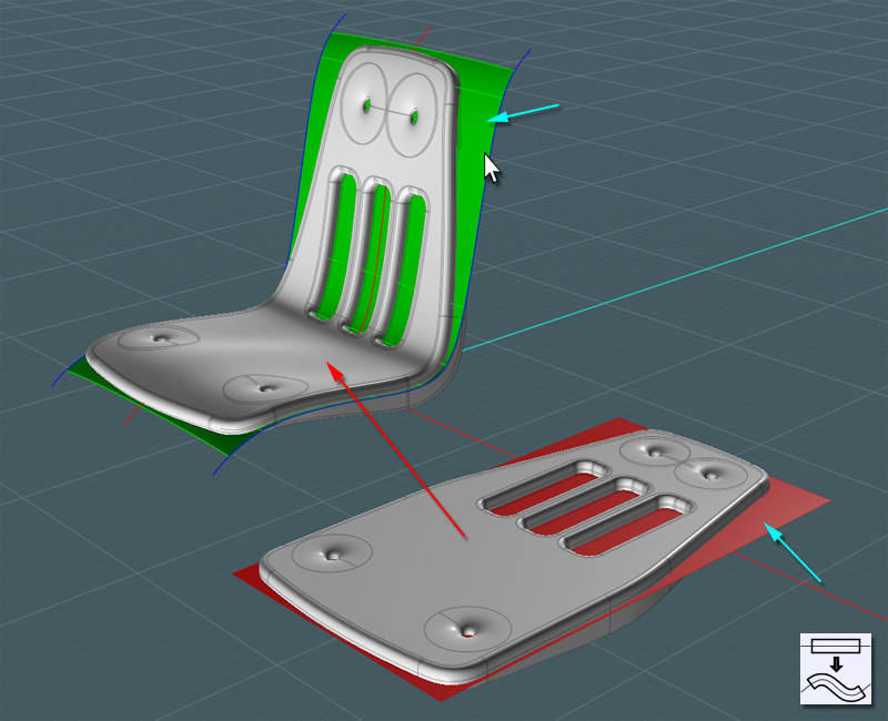
Using the new V3 Flow tool, first create a 'reference' plane. Place it somewhere in the middle of the 'mechanical' form.
Please note that you should not use a square that you performed Planar on or the points will be in the wrong place. Just use the Plane tool.
Use the Network surface as the Flow 'target'.
Here you go!
Here is the final chair shell form - which represents 80% of the work on this model... ;-)