Your common household plastic goods, especially containers for foods and cleaning supplies were most likely created with a NURBS-based program and sometimes represent some of the most elegant modeling work to be found.
Take a look at some of the detergent bottles on the shelves at your grocery store... take a good and close look at them.
If you're familiar with modeling in MoI, you'll start to notice some common design components such as Sweeps and Fillets.
Most likely, many of these commercial masterpieces have been created in an application like SolidWorks® and milled with a CNC with various solid and semi-solid materials and subsequently worked into a mould casing for an injection-blown plastic moulding process.
When these bottles are modeled, there are of course, many considerations that go into it, from consumer visual appeal to materials use, functionality, product dispensing and storage, and so forth.
Here, I present to you a relatively simple tutorial in the creation of another plastic bottle. But you can never have too much practice, especially with a program as beautiful and powerful as MoI! ;-)
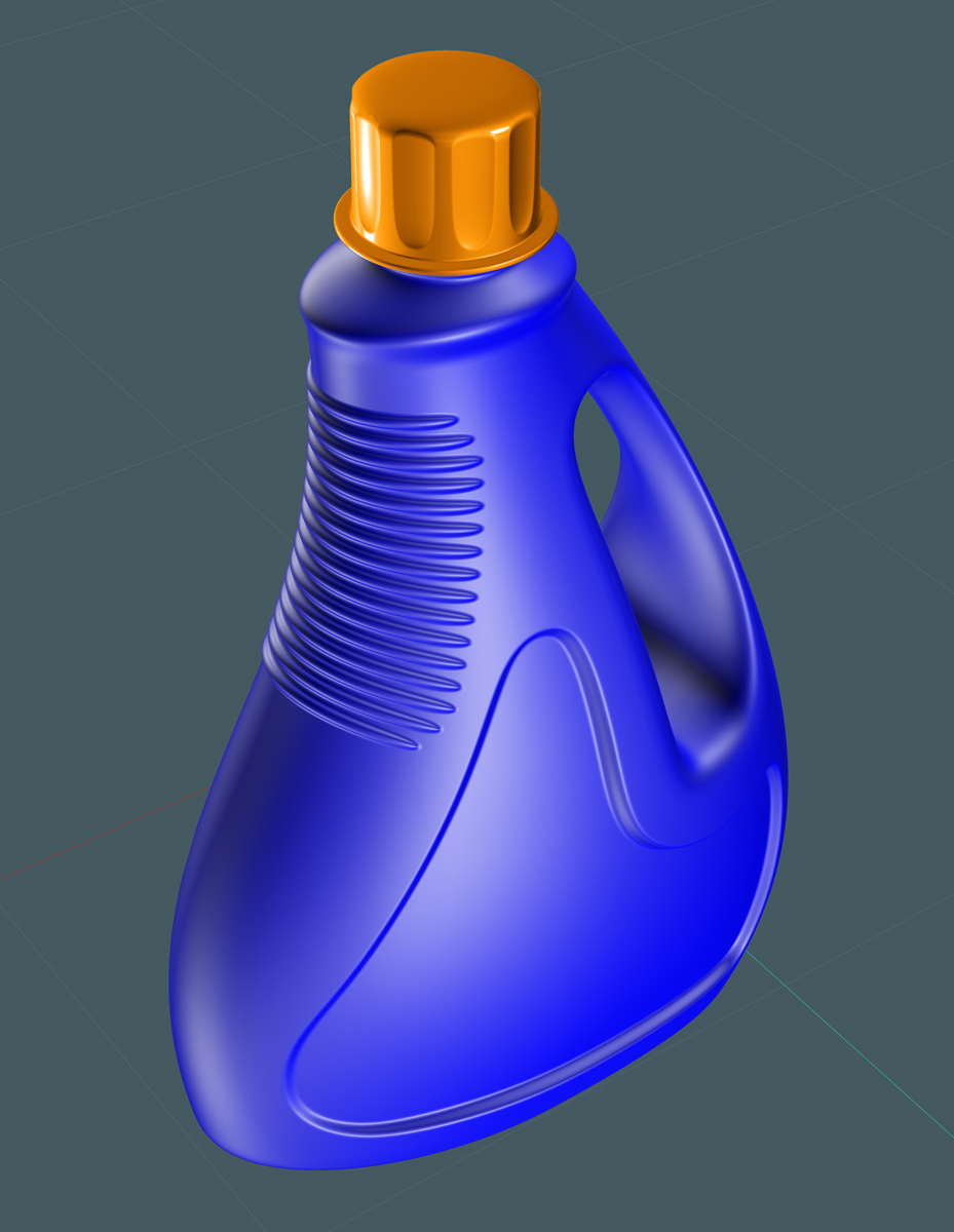
Since this bottle would be manufactured from HDPE
(Wiki) 
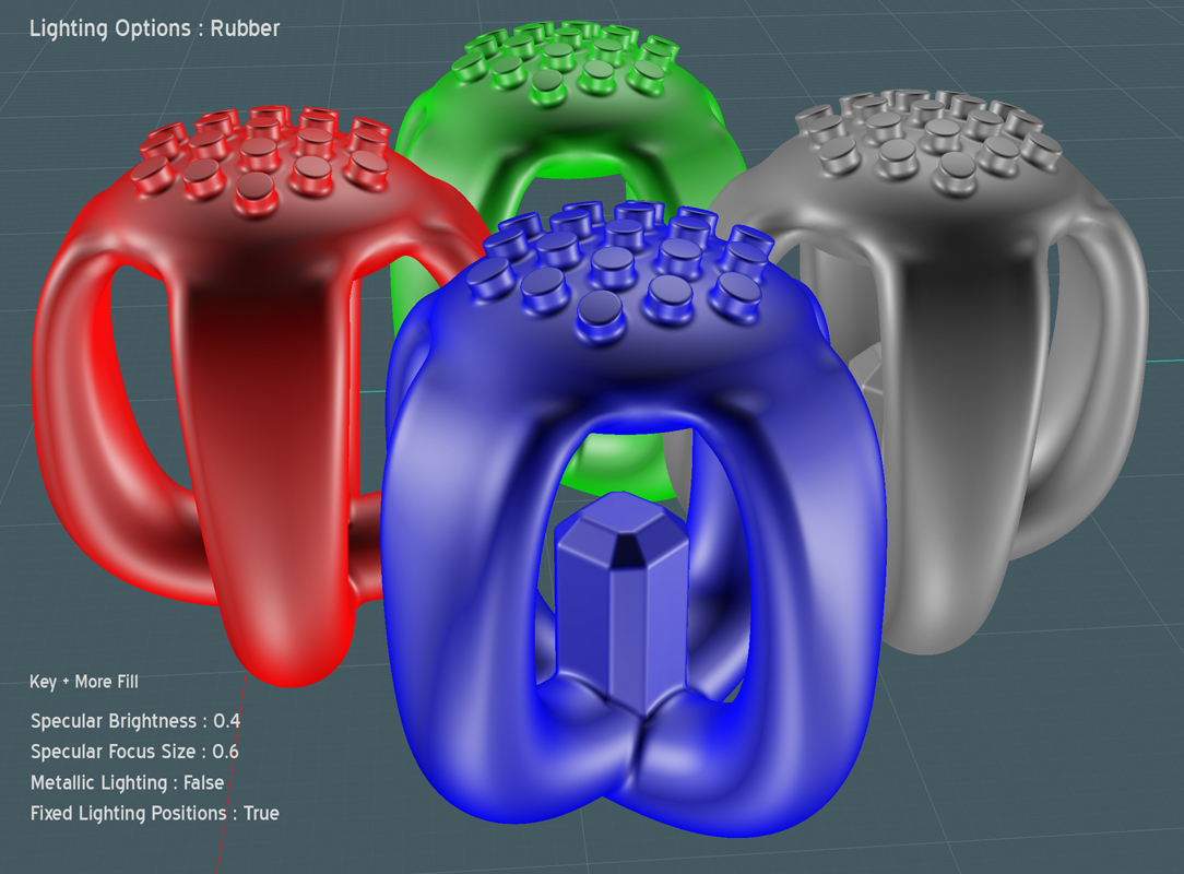
we could use a MoI lighting sceme that would inspire us in its creation.
Remember to write down your current MoI lighting settings if you use this:
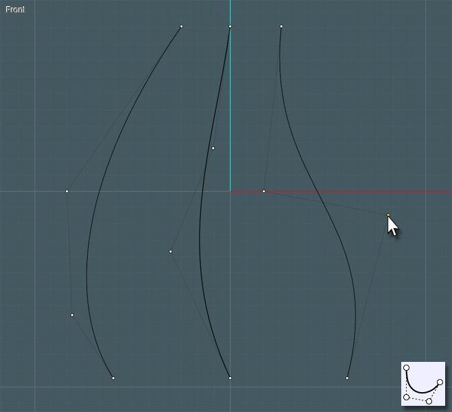
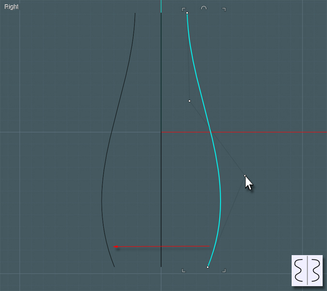
Let's start with the main body of the bottle. We can make this with the Network tool and we'll first start by drawing curves to represent the definition of the sides of the bottle.
Use the FreeForm or Through-Points spline tool and then go back after you activate Show Points and tweak the shapes to suit.
In this model, the left and right curves are drawn in the front view to represent the back and front edges - we'll be designing the bottle in its side profile, looking at it from the front.
Draw the middle curve as well. You'll use this to define the sides which will be symmetrical when you are finished.
If you cut the difference and average the shape instead of just drawing straight lines, the Network surface created will be very fluid.
Now all you have to do is create the "ring" profile curves for the ends of the Network surface creation.
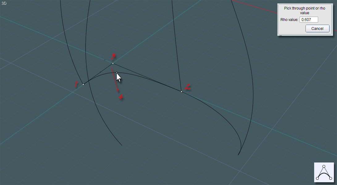
I used the Conic curve tool. Since I am orienting a shape that is symmetrical in the cardinal directions, then drawing the Conic curve by making guidelines in the X and Y, if your first three clicks form a 90 degree square than the final click and drag will determine the shape of the conic curve.
It will give you an attractive squarish round shape that are great for bottles.
Join those curves to make single rings.
After you make one side, you can simply Mirror the result over the center line to make a symmetrical shape.
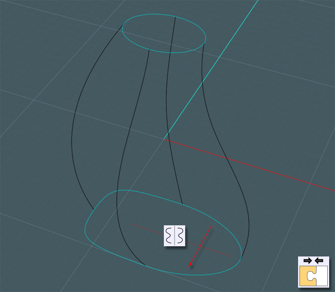
You'll have to make one to represent your desired shape at the top and the bottom.
Apply the Network tool to your selection of the four profile curves and the two end profile rings.
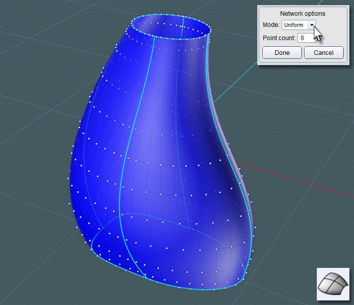
With MoI V3 you can control the distribution and makeup of the surface point structure. Find one that makes it look nicest. I used "Uniform".
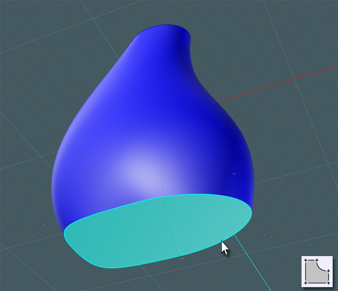
Now to make the bottom of the bottle. Simply select the profile ring and make a Planar surface. Join that to the main shape.
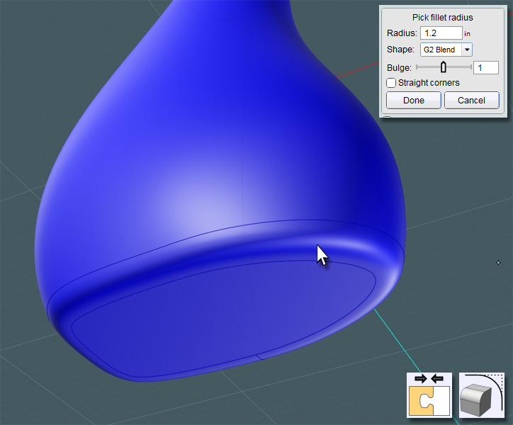
A nice G2 Fillet will make a smooth overall shape.
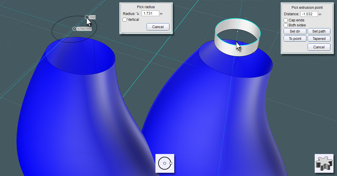
Now for the top... You can simply draw a two-point circle, and if you use the C-Plane center, your future work may be easier.
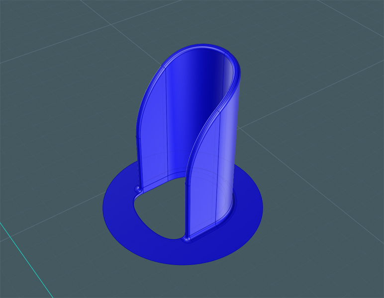
I would like to make a Blend surface here to form the top - Extrude the circle so that you have two surface ends to Blend with.
Again, using the G2 mode will make for a really smooth transition.
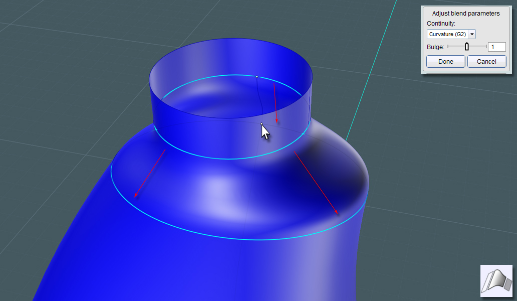
Get a handle on it!!!
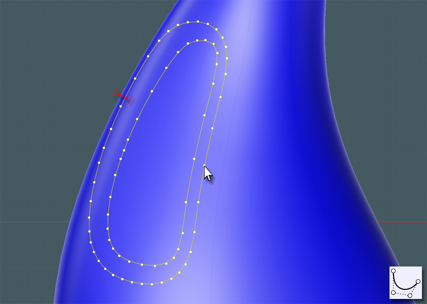
We need to make two closed curves to represent the start and finish of the Blends to surface the inside of the handle.
Draw these in the Front view so that you can project the shape through the side.
Keep the larger one near the edge of the bottle shape so that the handle shape you create is just the right size.
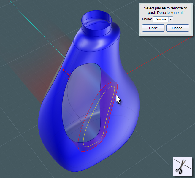
You can Trim if you like to take the larger shape away from the bottle's main surface.
However, it might be better to use Projection and then Trim the projection because after Projection the history state will allow you to adjust the result on the main surface before Trimming. This way, you can get the perfect width remaining for the handle's grip area.
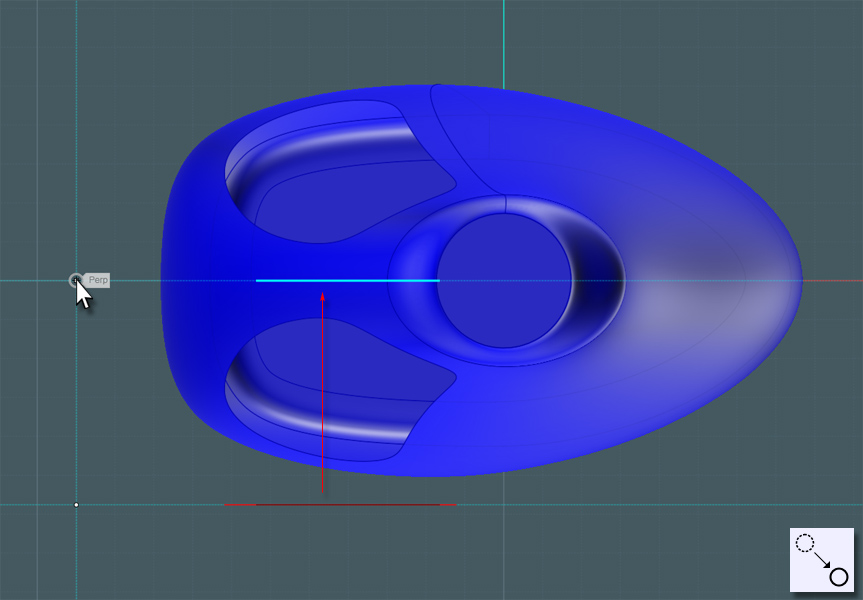
Now that you have the outside areas cut away you'll need to move the smaller inside profile to the center of the bottle to work as the other end for your Blend surface.
Extrude this smaller ring.
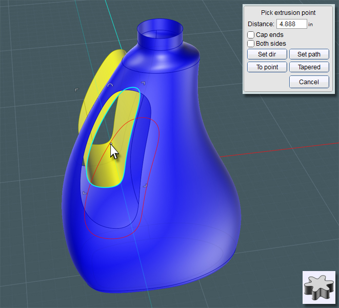
Another G2 Blend will give you a smooth shape. This will be one side that will have a symmetrical component.
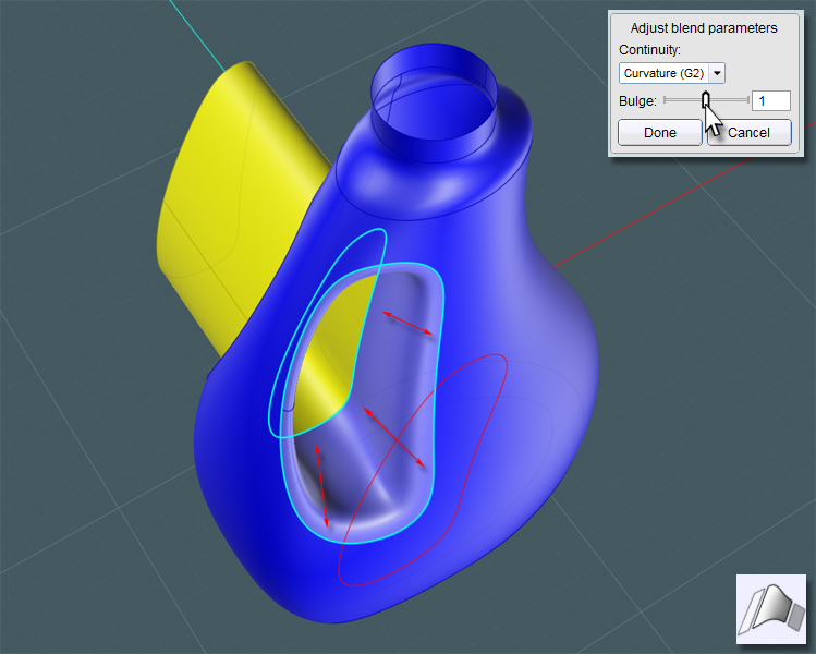
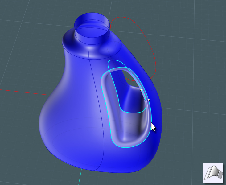
If you look from the other side and delete the extrusion reference surface you used for the Blend, you can Blend between the other opening and the inside edge of the Blend to create the symmetrical surface counterpart. The entire set will have smooth continuity.
Now for the Bottom. Providing a ridge lip on the bottom provides structural strength to the bottle which is made of thin plastic.
You'll notice that there are concaved areas on the bottom of most bottles and some are quite complex looking with all kinds of protrusions and ridges.
These areas do three things: 1) Add structural stability, 2) Adds a means by which to hide the plastic blown-mould pour port area, and 3) A more pronounced and larger concaved recess area actually steals more container space from the bottle. This is the way manufacturers hide the fact that they are "down-sizing" the volume of a product's container without making the product look visually smaller! (Dirty secret)
I saw a plastic peanut butter jar one time with a two-inch bottom concave area. Did this container need that much structural integrity - I mean it's peanut butter! Where's it going?
Offset the profile ring on the bottom. Please retain the original ring shape. The edge curves from the Fillets are often unpredictable.
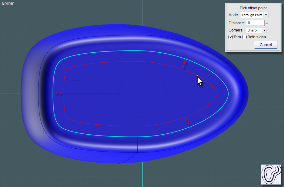
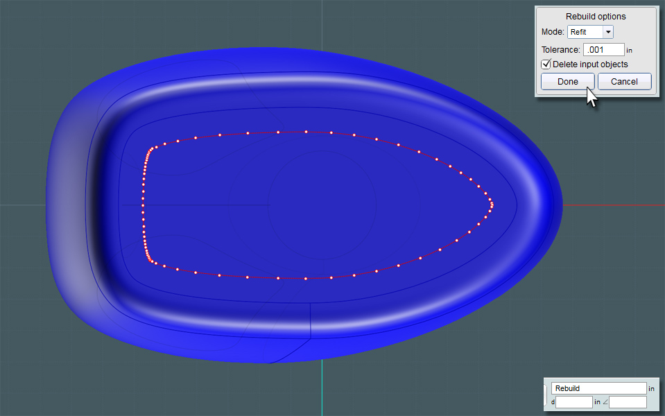
Rebuild the closed curve to help clean it up. You should also consider Fillets and other rounding techniques as you'll need this to create a Blend surface.
To make a recessed area, use Trim to take away a small space in the bottom surface plane, then move the inside plane up a little. Use the smaller profile ring to make a Planar shape if need be.
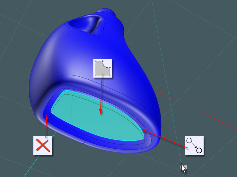
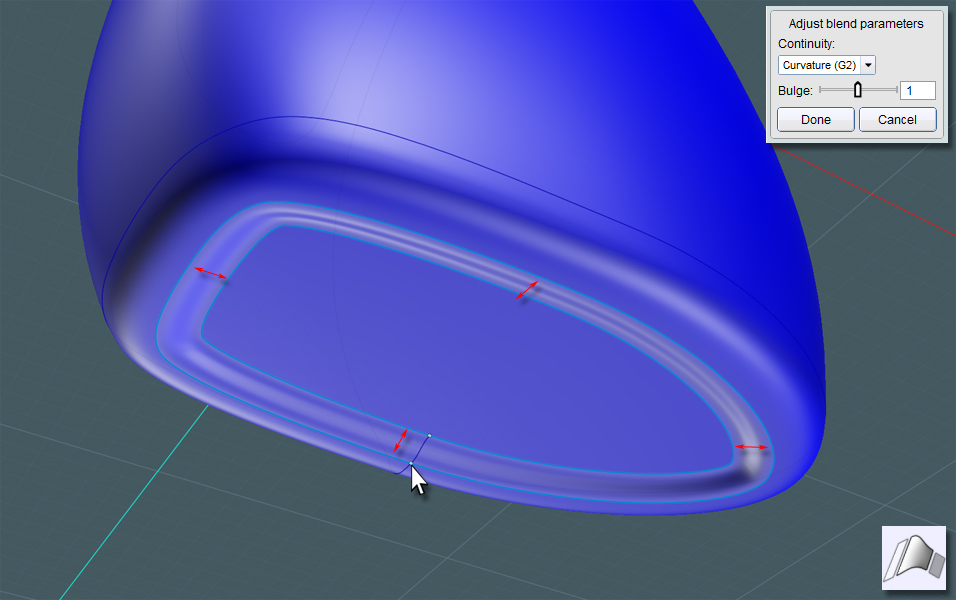
Now Blend the surface edges and Join.
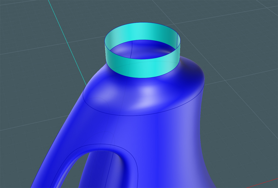
The extruded cylinder ring at the top of the bottle was really made for a Blend reference edge just as in the handle area.
Select this surface and Isolate it or hide everything else. We'll be creating the top cap-screw and spout.
You can go to town with a profile shape that you'll be Revolving to make the basic spout objects.
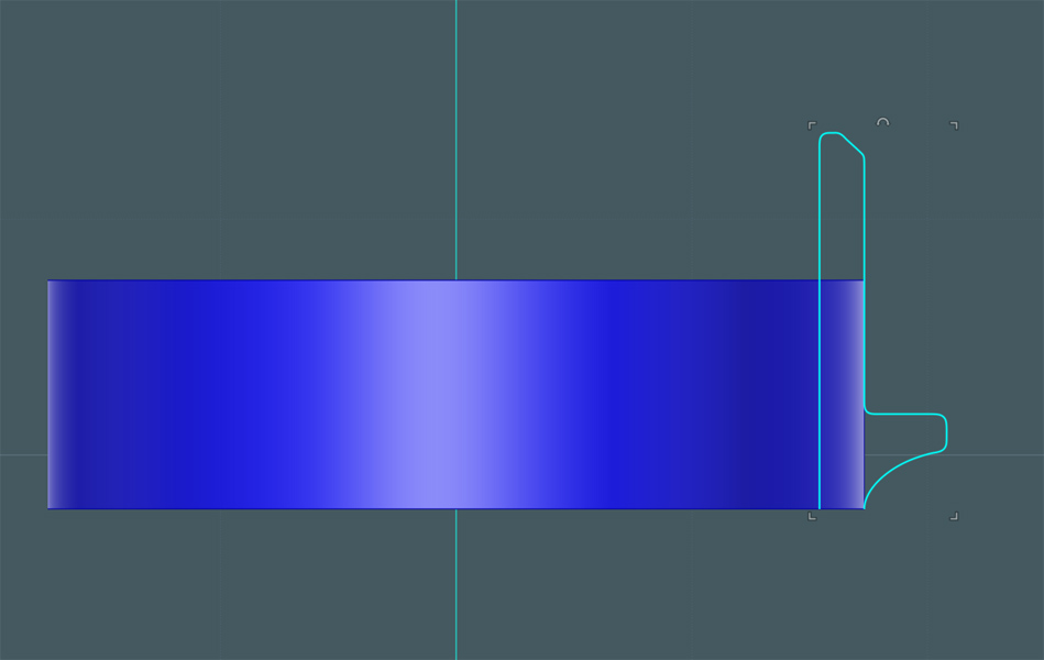
Revolve this profile...
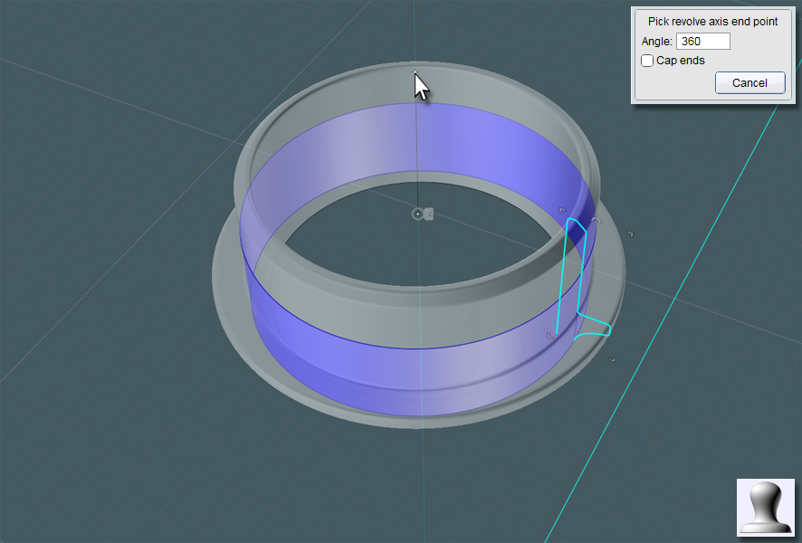
A happy accident!!
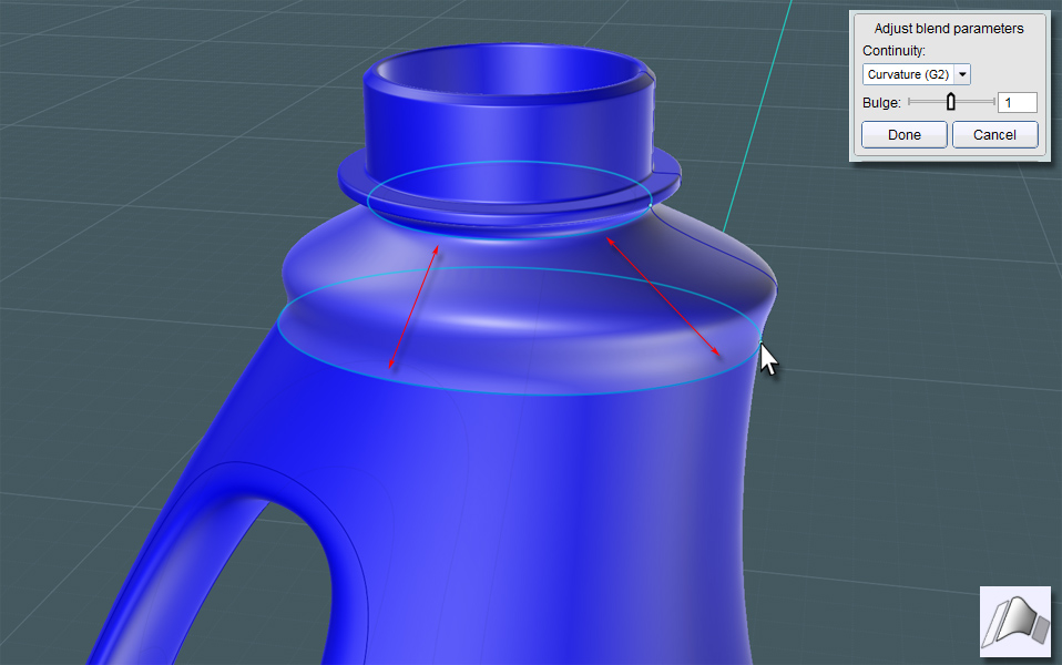
It might be a good idea to create a new Blend that will truly match the revolved surface, just in case the revolved surface isn't perfect.
When I made this G2 Blend, this funny lip protrusion occurred in the surface!
The logic on why it did this escapes me - maybe someday we could perhaps control the Blend with some kind of handle bars.
Though, I like it! This looks way cool for the top of the bottle... Almost as if it was planned! So I'll keep it.
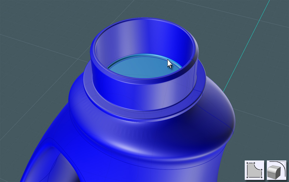
Next, I made sure that the inside of the spout had a solid floor. This could be made with the profile, but here, by making a Planar surface, there is no seam to deal with.
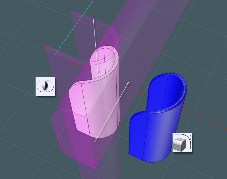
Here's a neat trick: Take two profiles - a 'U' shape and a side profile and Boolean Intersect them to make a new solid.
Just Fillet the edge and now you have a pouring spout.
If you can segregate the floor surface, you can work the spout object into it.
Re-Join this part into the bottle spout.