> Hi Mike, ok but what I have been trying to describe is that all you need to do is run Rebuild on that bendy curve and then after you have done that the rebuilt version of it has "arc length parameterization" - meaning that it will be a match to a simple single line as far as traveling along each in a uniform manner.
Thanks Michael, that has awesome potential!
Let's take a look at how to implement this:
PREPARATION FOR FLOW BY USING REBUILD+
UNWRAPCURVE

(looking at the pic)
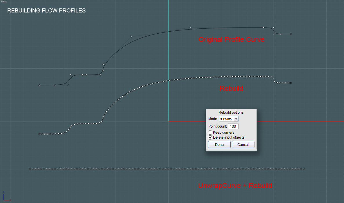
The first curve at the top is the original spline representing the profile of our TARGET Flow surface.
The second curve in the middle was derived from the same profile curve using the Rebuild command. I chose 100# points, which as Michael pointed is used to build arcs or (near) even displacement along the curve's path.
The third line was derived from the profile curve using the new UnwrapCurve script.
It has also been rebuild (Rebuild) using 100# points, though it is still straight.
The advantage of using UnwrapCurve is to derive a line that is a close approximation of the true length of the profile curve when it is stretched out.
Therefore, when used as a Flow target, there shouldn't be too much overall length or dimensional distortion in the final result.
The goal is to make the original objects appear to flow along a surface naturally.
Now I'll use the profiles:
Note - You can also rebuild and unwrap curves (up to all four sides) to make a more complex Network.
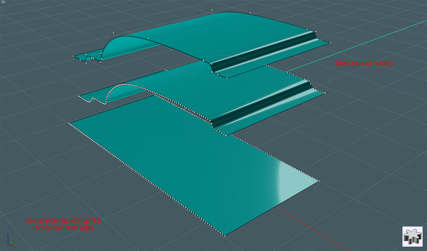
In this case, I Extrude the profiles and the line in order to create Target and Reference surface to try Flow with.

As you can see in this pic, the underlying points (isocurve) structures of these surfaces are constructed from the points within the profile curves.
These underlying arrangements will determine the the final placement of the flowed objects regardless of the appearance of the surfaces.
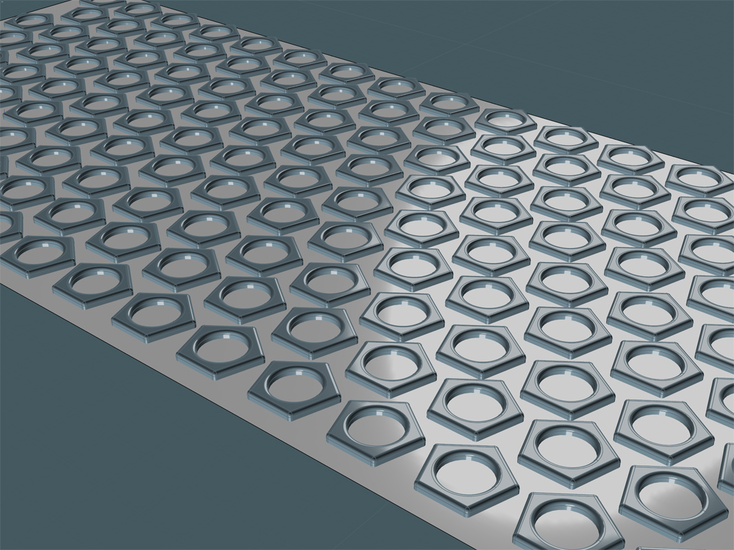
Here, I'll create a nice pattern to be flowed onto a surface created from my original profile:

I chose these pentagon/circle shapes to make a test pattern. Their shapes make it easy to see any relative distortion on the spatial arrangements when flowed.
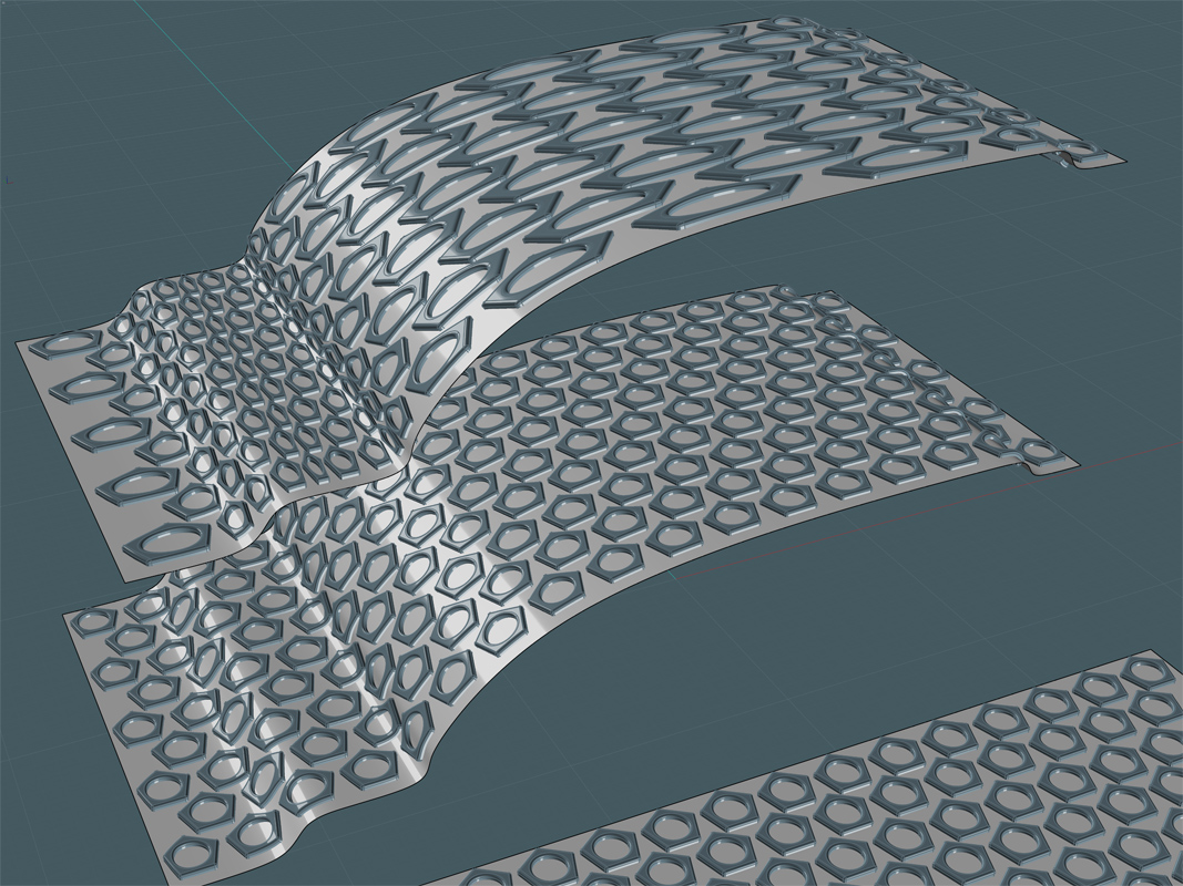
And here is the result!:

The Flow result on the top surface derived from the original profile curve has an awful displacement. (awful for what I needed in this instance) The distortions follow the "parameterization" of the control point arrangement in the original spline. This effect has advantages too and allows you to do neat things where this type of distortion is needed.
Ah! And you can see the Flow result in the middle. It has a very consistent-looking displacement.
For the Flow placement of shallow object arrangements, you can get very natural results this way.
Of course, the displacement of a flow is most accurate at the base surface level. As you move through the W (above and below) of the surface, distortion will occur due to the variances in the angular re-arrangements of the flowed objects. In other words, pinching and expanding will naturally occur.
I'm curious to try both a U and V arrangement.