Part Four: The Adjustable Shower Bar
This is the assembly rigging that holds the shower head handle and allows it to adjusted for use.
You can also attach other items, such as an adjustable shampoo and soap tray.
It's very basic. Just a bar and two braces to hold it to the wall.
But most of the work will be invested in the fru-fru rococo-ness of the assembly's superficial design. ;-)
First we take the escutcheon cover that was made earlier and place two of them as they would be on the shower wall above the tub or shower floor.
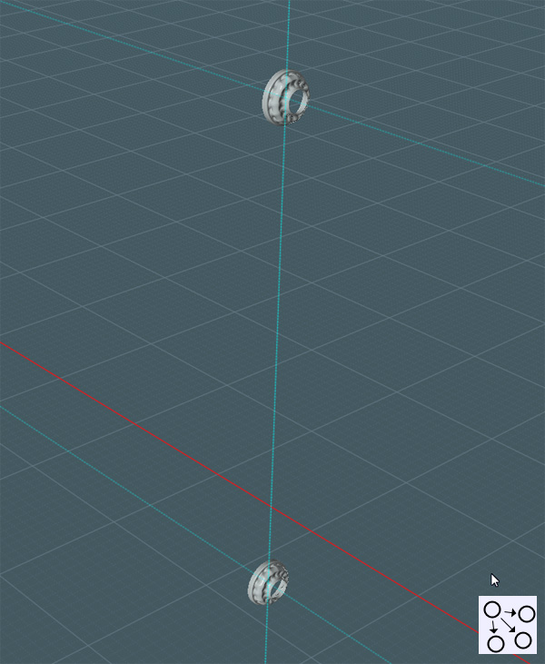
The center hole in the cover was made to be 1.5" d. To make an instant pipe, simply Extrude one of the center circle shapes.
This will complete the brace.
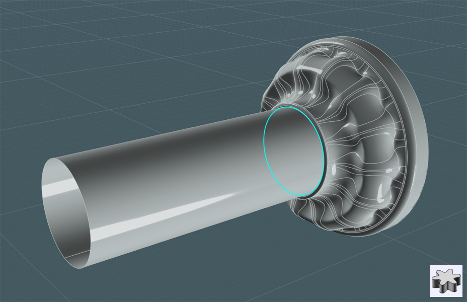
Use construction lines to infer the pipe sizing to create a circle for the vertical bar, (or copy the extruded object).
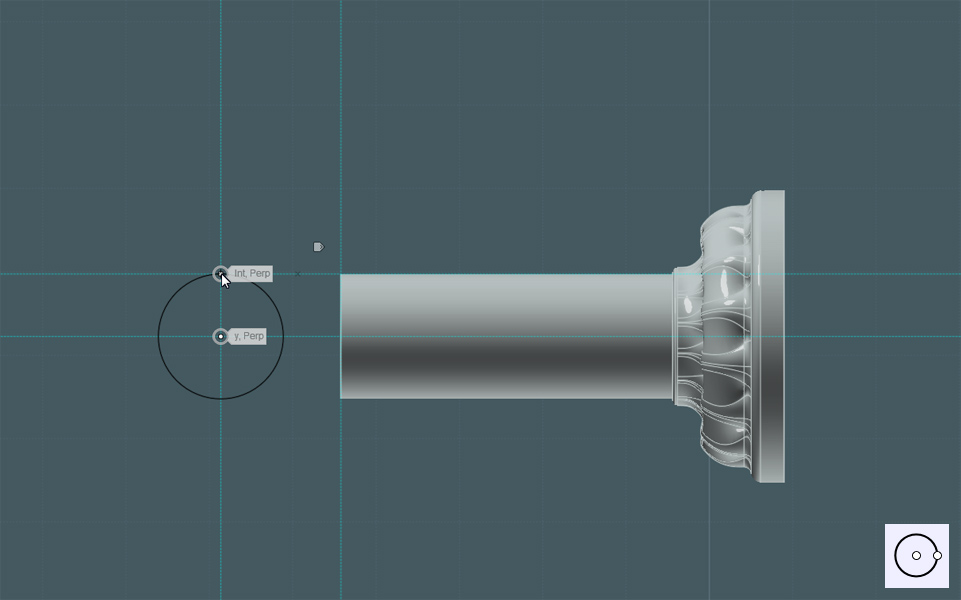
And Extrude the circle. Any length will do.
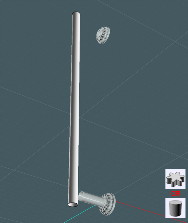
Later, I'll be replacing this bar with one having a little more detail.
Here is where you can have a little fun:
Create a profile with your curve and line tools. Then Revolve the shape to make an interesting object to act as the bar and brace union section.
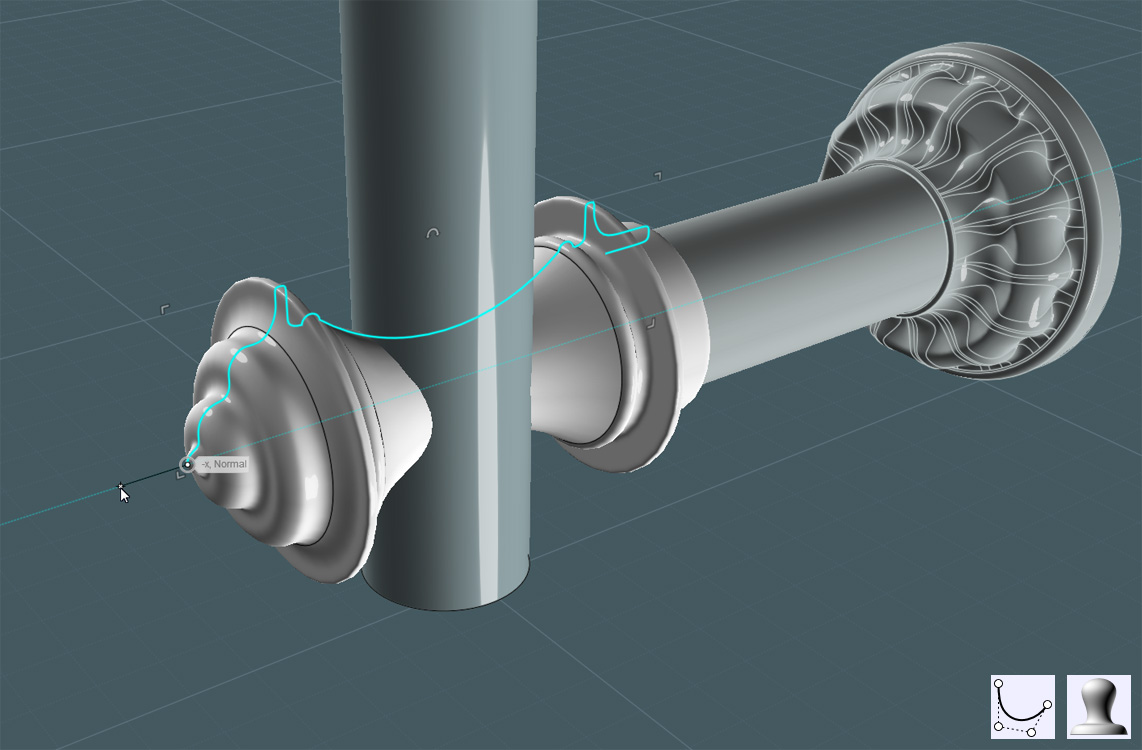
Why not decorate it?
I created a small Sphere in one of the circular areas and sunk it half-way into the object. Then I Circular-Arrayed copies of it.
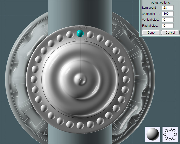
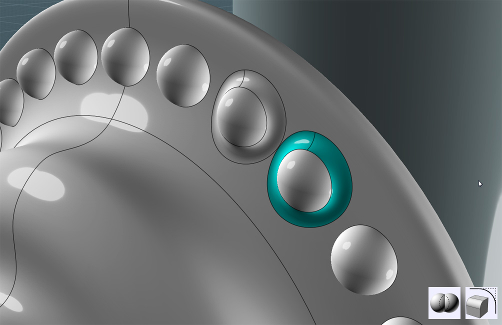
And to give the decoration a real molded/pressed look I Boolean Unioned the spheres and Filleted the resultant mating edges.
I created a profile shape and Revolved it around the vertical bar.
Inside of this piece would be a nylon friction sleeve and the housing for the friction lock.
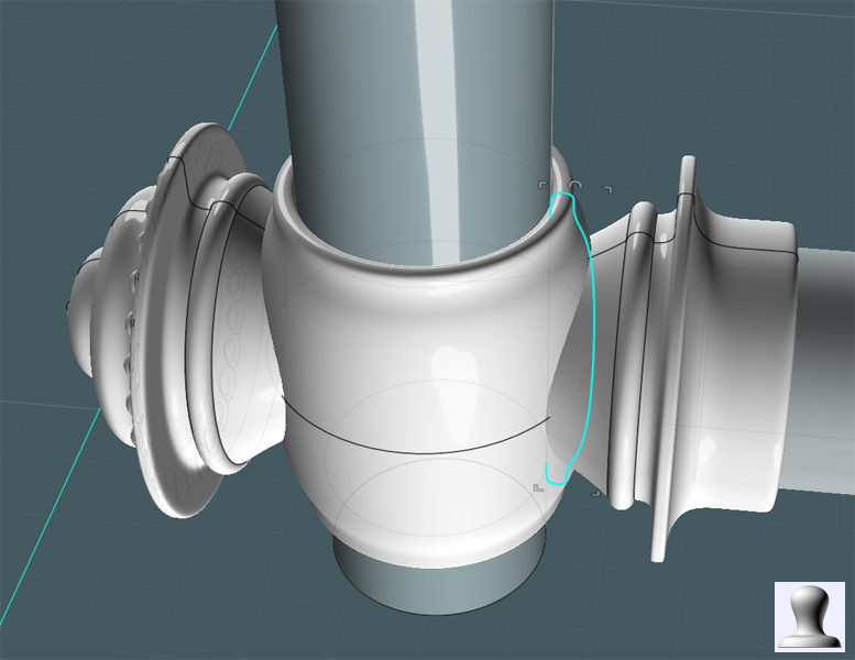
Union the two revolved objects together.
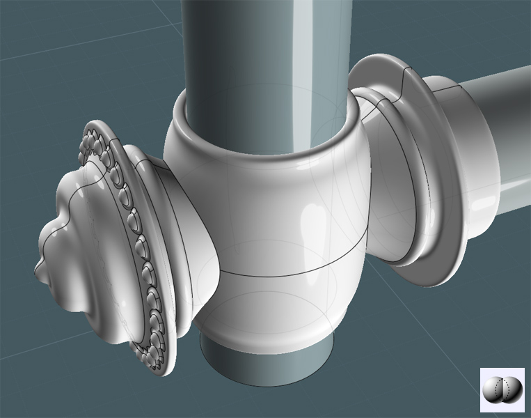
Simply Fillet the mating edges to make a smoothed transition.
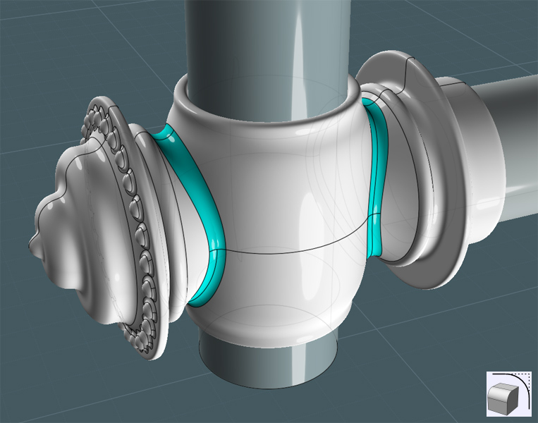
Okay... There's nothing simple about this. This is my second attempt and the Fillets did not want to take until I re-Revolved a new center shape. You may also try Difference cutting the shapes into sections and Blending their edges.
This bar is adjustable. So there has to be a frictioned tension adjustment knob on the side.
Yes, there are braces that would essentially be fastened to the wall in fixed positions, but there is still a need for lee-way with attaching extras.
And this model illustrates the principal of the design.
Create a couple of circles from the center of the vertical bar.
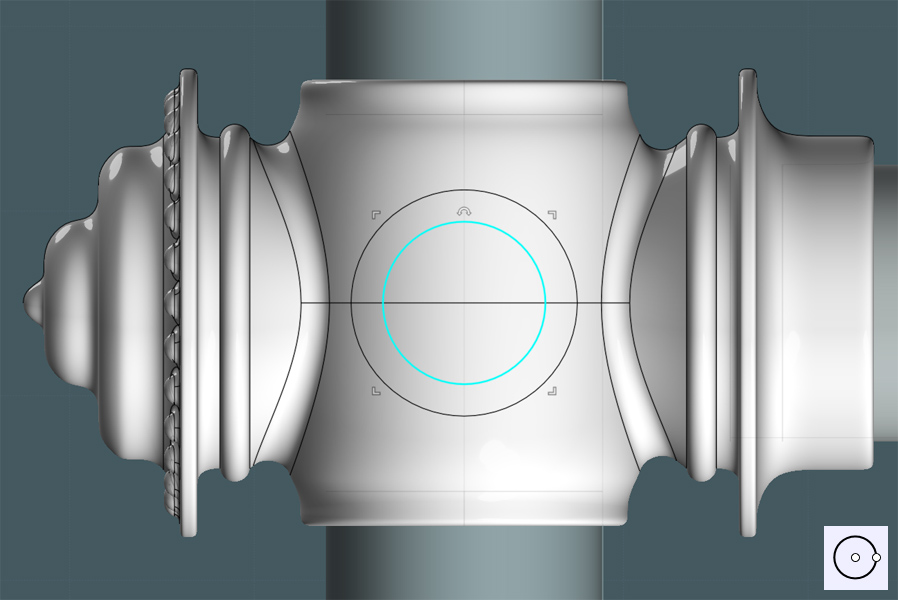
Make a Projection of the larger circle to the side of the shape.
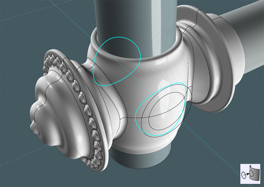
I trimmed a larger circle out of the main object's side and made the inner circle Planar.
Yes, I want to Blend the surface edge of the hole in the side to the edge of the planar circle.
Because the main object has a seam line running through the middle of the hole, I Trimmed the edge curves with "Add-Points" to create two matching edge sections.
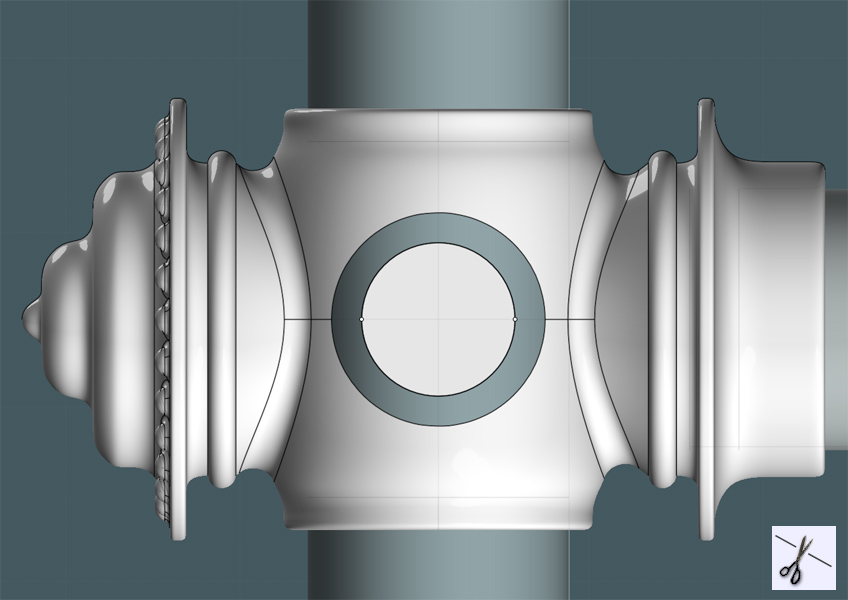
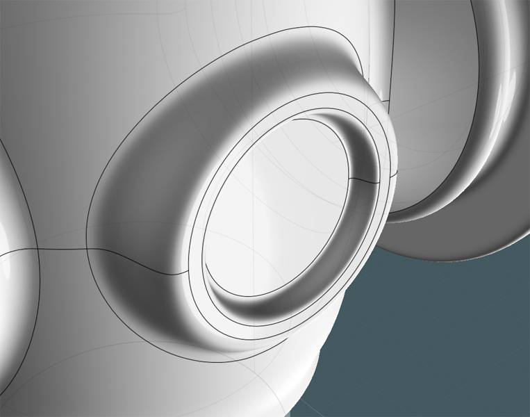
I Blended the edges and then joined all associated surfaces.
As you can see, there is now a smoothly made protrusion from the main object's side.
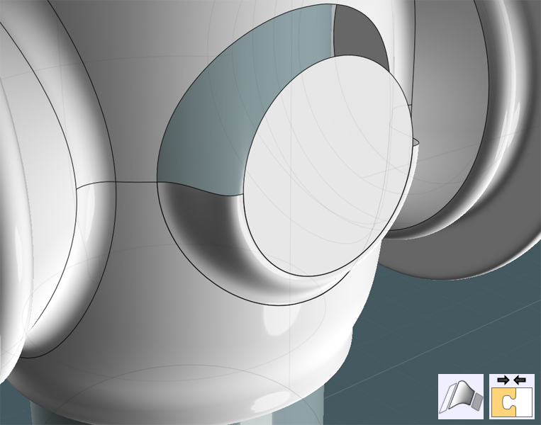
I did a similar procedure to create a custom inset.
Here, I'll make a knob to go on the side. It will have a floral look to it.
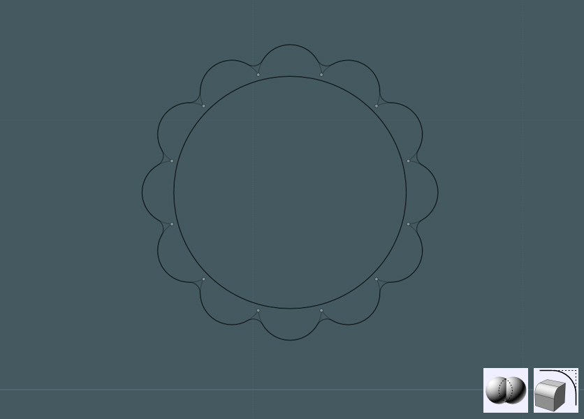
So, Let's create a small circle and Circular-Array it around a center point making sure that the circles overlap.
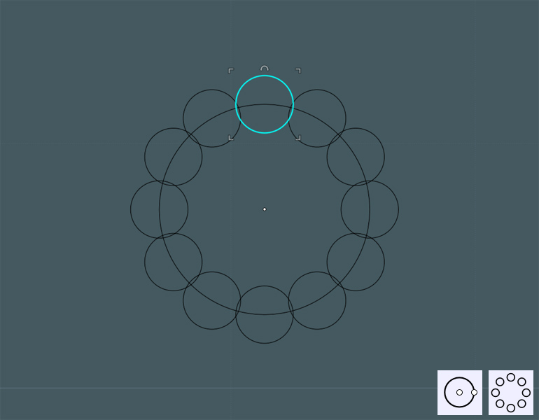
Boolean Union the circles and delete the remaining inside shape.
Fillet will smooth out the sharp creases...
Now we will use MoI V3-Beta's new "Majik Cloud and Rainbow" maker... You do know about it, right? ;-)
Just kidding! A little Photoshop to show effect.
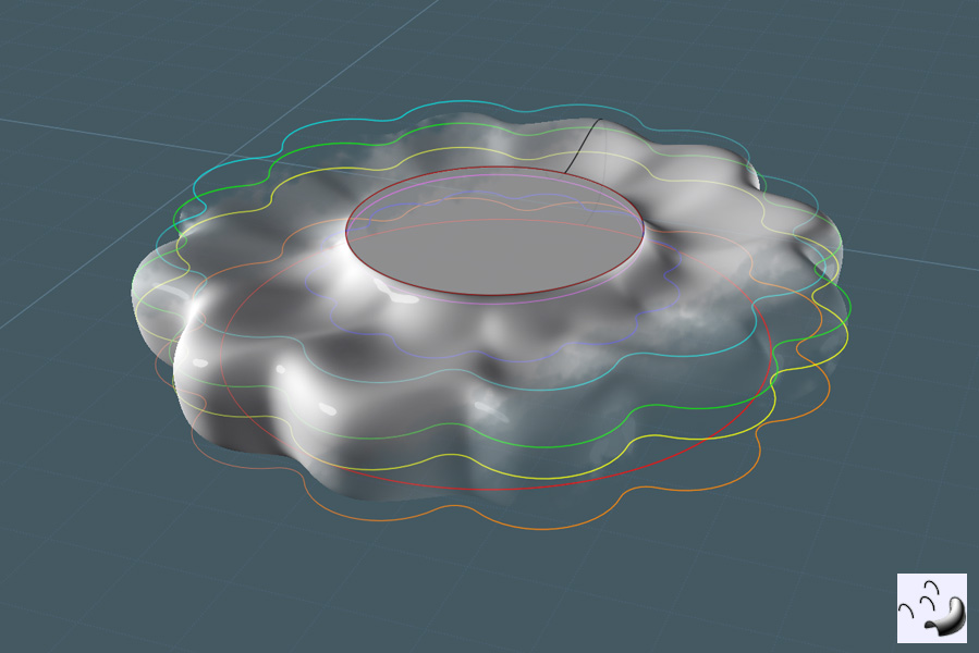
Here, the floral shape was copied and arranged - and a few circles were also added.
The image below illustrates that (following the color transition:) a Loft was then performed with profile rings that were selected in the order by which the surface was created.
In this example, from top to bottom. The Loft command was set to the "Loose" setting, and a neat floral shape was produced.
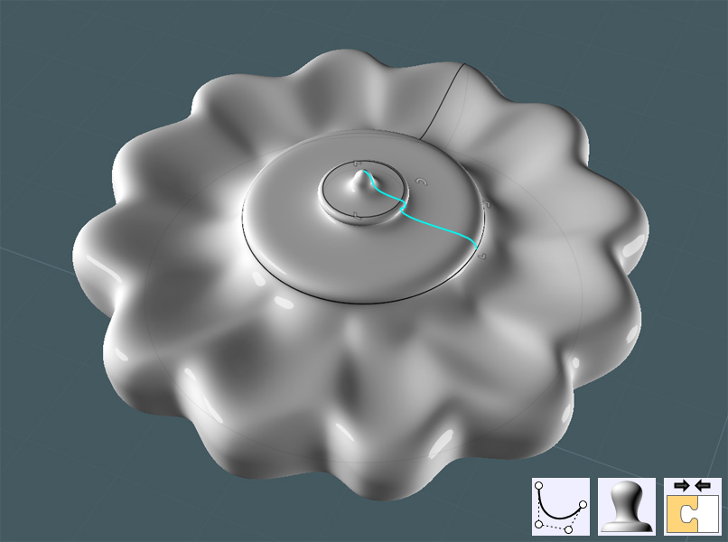
A Revolved profile completed the tension knob object. An extruded circle was made from the bottom to create a bolt.
All surfaces were Joined together.
The tension knob was rotated, and moved to alignment with the main object.
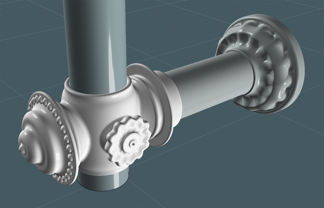
A copy of the entire brace and union set was copied to the upper part of the vertical bar.
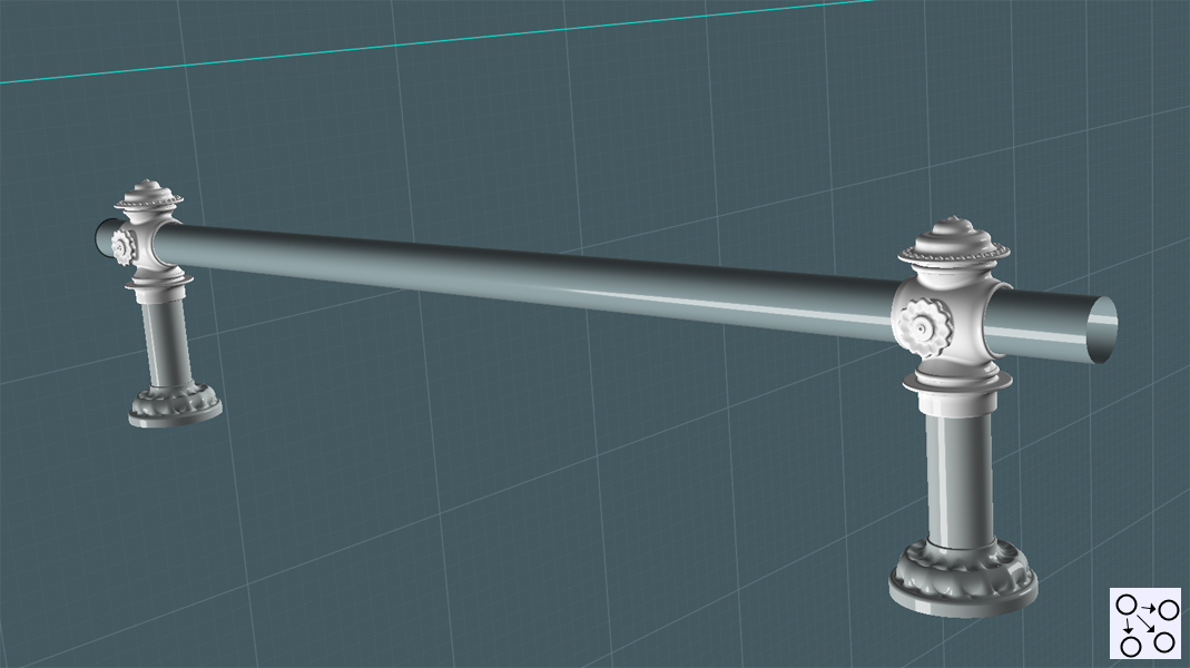 As you can see - this model can later be recycled to make decorative walk-way rails. Yes mates - Queuing in style!
Now to cap the bar ends:
A profile curve is made and Revolved using the center snap point of the vertical bar's bottom circle for the axis.
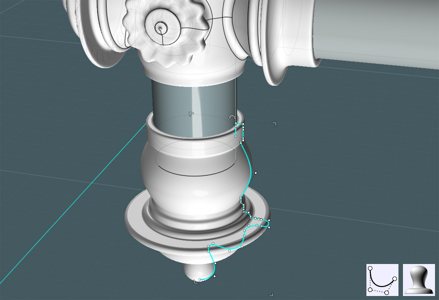
I made a broad curved space to add detail like fluting.
I made a Freeform curve to mimic the edge of the revolved surface.

I played around with a few different shapes to work with, but settled on Sweeping two profile ellipses to the rail curve.
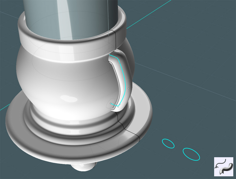
If you place the profile shapes for the Sweep below and away from the imaginary boundary box of the rail curve then MoI will take those shapes, one by one - as arranged and performs a Sweep merging the shapes along the path.
Here I then did three things:
1) I moved the Swept shape so that it sunk a little into the revolved object.
2) I performed a Circular Array to the shape around the revolved object.
3) I Boolean Differenced the main revolved object away from the Swept shapes, leaving curved surfaces.
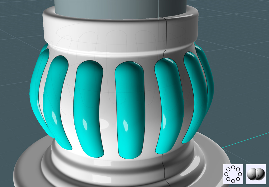
You can simply Boolean Union the Swept shapes to the Revolve shape - then Fillet their edges.
But the Fillets didn't work........
I needed to make edge Blends instead.
I wanted to make the shapes smaller. So I created a profile curve to act as a cutting shape.
Working in a side view was good for visualizing exact placement.
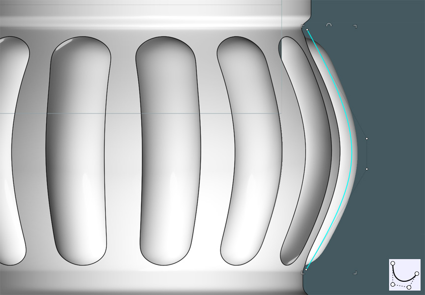
I revolved the profile with the ends capped and trimmed that resultant shape from the curved surfaces.
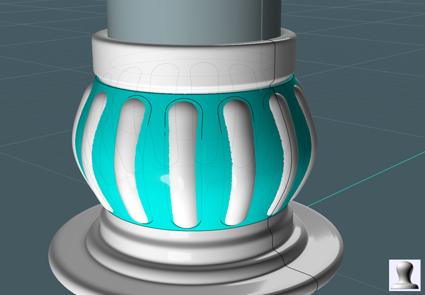
I failed to show a few steps here, but needless to say, this is up to your own discretion.
I created a larger (or offset) shape that was also circular-arrayed, Projected and Trimmed from the revolved object's surface.
I then Blended the surface edges of each object.
This gave me a more smooth transition between features.
This was not without trouble as well. I had to both Trim and "Merge" many of the curve segments that were broken up on the edges.
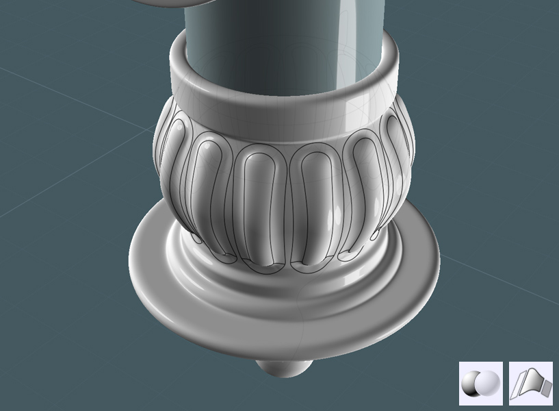
Just simply copy/flip the cap section to the other end of the bar.
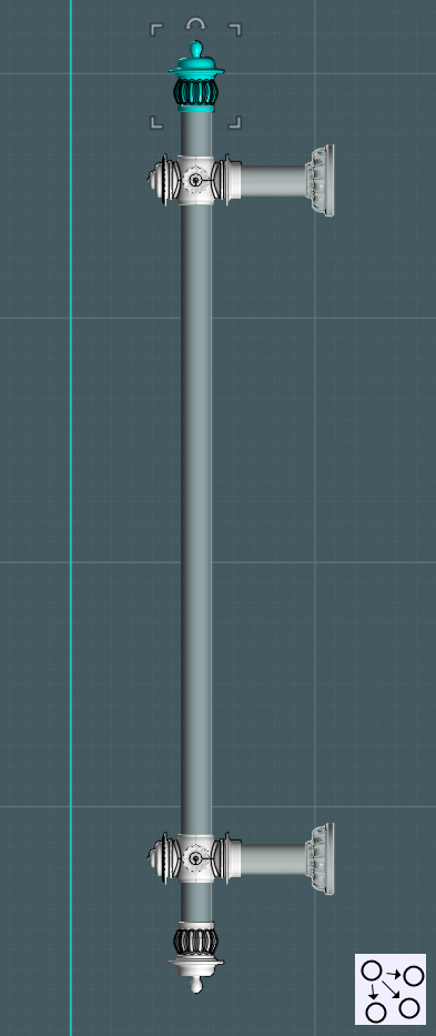 Whew!
Whew!
I had a bit of trouble getting this part done... My home PC had a few technical glitches.
Both a video card and power supply unit had to be replaced! Noooo... I believe the PSU might have ruined the vid card,
or that lightning got both at one time... who knows.
But most likely - it was a lethal combination of NEGLECT and the caking of dust! The poor ventilation and 24/7 operation may not have helped much either. :-o
None the less -
In the next one or two sections I'd like to finish up the shower head model with some extra details being added to the frame.
And also, the modeling of the helical metal water supply hose.
Then later a few good renders after I model up some control fixtures.
Please Visit http://k4icy.50webs.com/tutorials.html for more Tutorials!