I may try to create a better example later to show what I'm seeing in my head.
Here is an example of what I do to mimic the "straightened out" spacing of a more complex curve in order to flow something to it.
In the following pic, there are two curves. The top one is a curve with all kinds of bends and curvy stuff happening to it. - representative of my target flow surface.
The lower curve is one I made by hand with a spline tool. - straight, to use as the reference surface. I had to guess to approximate how far it was between each control point, as if I was able to stretch the top curve out straight.
The c-lines are just there to show the relationship between the original curve and it's control points to that of the straightened-out version.
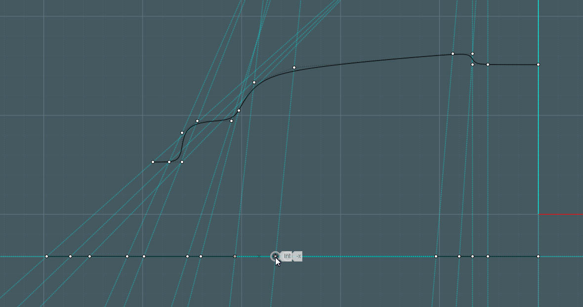
I used these curves to revolve them into circular surfaces, but it also works for a non-revolved flat surface if I simply extrude both of the lines to form rectangular surfaces.
Of course, just throwing control points along a straight line is not going to work accurately by eye, because the above control points of the shaped curves do not represent the true on-curve distance, they are used for spline control. But I can't think of any way to figure it out.
(man, is this an esoteric conundrum!) |