Back to reference index Prev page Next page
Construct
 |
| Boolean |
 |
| Union |
Fuse objects together where they intersect.
Solids can be unioned with other solids or
surfaces, and 2D curves can be unioned with other 2D curves.
The Boolean can be limited to only intersect with specific faces
of a solid and ignore others by making a face sub-object selection before doing the boolean
rather than selecting entire objects. This can be useful to union just to one side of a thin
walled object.
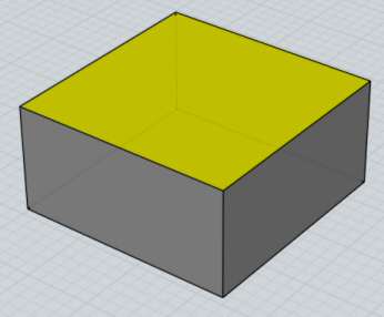
Here's an example of unioning 2 solids - at the start there are
2 different box objects. The skinny box is positioned so that it punches
through the wider box. After selecting them and running Boolean Union,
the boxes are combined into one object. New edges are formed where the
boxes intersected each other, and portions of each box that were inside
each other have been discarded to make one single connected volume.


Curves that are all on the same plane can be combined in a similar way:


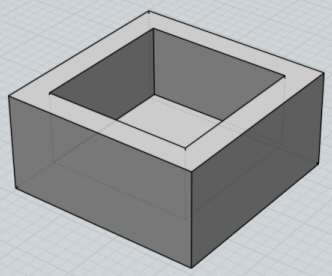
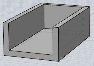
An example of subset booleans, where the boolean is limited to a specific area by face selections.
Here are 2 solids pushing through each other:
If only the outer face sub-object of the other object is selected instead of the whole object, as shown here:
Then when doing a Boolean Union, only the outside face will get intersected and the unselected faces
along the interior will be temporarily ignored, producing this type of result:
This can be useful for combining objects on only side of a thin walled object.
 |
| Isect |
Combine objects together, only keeping areas contained by all objects.
Objects to be intersected are treated as 2 different sets. Select one set,
run Boolean Intersection, then select the other set.
Solids can be intersected with other solids, surfaces, or curves, and 2D
curves can be intersected with each other. 2D curves that are all on
a single plane will generate a curve result, or 2D curve profiles on different
planes can be combined to generate a solid result.
Example of solid/solid intersection:


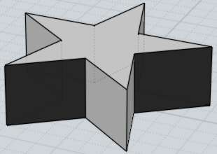
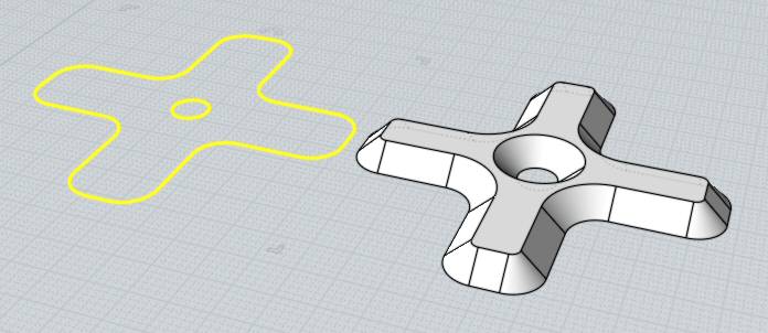
Here is an example of intersection between a solid and a 2D curve. The
area inside the curve will be kept. In a sense this is the opposite of
Boolean difference, which would instead drill a star shaped hole through the sphere.


Boolean Intersection can also be useful for creating a quick blocky 3D model
that is the combination of 2 2D profiles arranged 90 degrees to each other.
For example, here 2 curves are intersected to create a basic blocky car shape.
History is available for this type of intersection, so you can adjust the
curves and watch the 3D result update.


Another example of combining 2D profiles - final stage shown after using
Fillet to round the sharp edges:


Boolean Intersection can also be used on curves that are all in the same plane
to create a curve result:


Another curve intersection example:


 |
| Fillet |
|
| Fillet |
Fillet is used to round off sharp corners.
Fillet will apply the rounding in different ways depending on what is selected.
Selecting an entire solid object will fillet all edges of the solid.
Selecting edges of a solid will fillet just those edges.
Selecting faces of a solid will fillet all the edges that belong to those faces.
Selecting 2 individual surfaces will perform a surface/surface fillet operation, instead of an edge-based one.
Selecting 2 curves will create a fillet between them, extending or trimming them if necessary.
Selecting a single curve that has corners in it (for example, a rectangle curve) will allow filleting
of some or all of those corners.
Some examples of filleting:


At the "Pick fillet radius" prompt, you can either click 2 points to define the radius as
the distance between those 2 points or enter a radius value directly. If you want to type in
a value, it is not necessary to click in the Radius edit box first, you can just start typing
and keystrokes will go there.
The Shape: option controls whether the fillet will be shaped as an exact arc or as a more
organic blend type shape. The blend options show a slider that can be used to adjust the amount of
bulge.
The Straight corners option controls whether rounded corners will be placed where fillets meet,
or whether the fillets will be extended to intersect each other directly:


Enabling straight corners will cause failures in some situations where the fillets do not directly
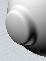
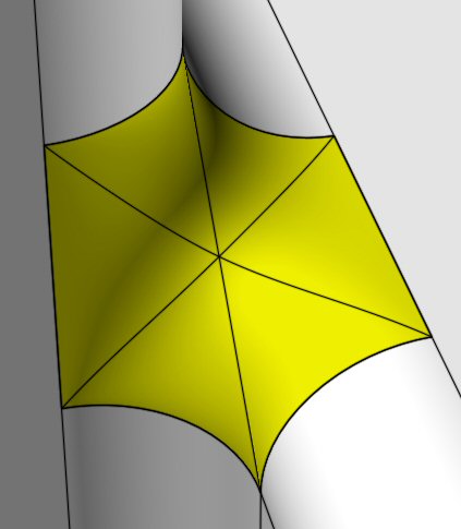
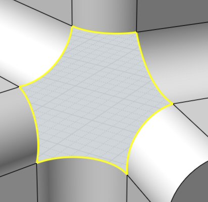
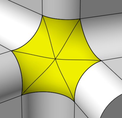
intersect each other when they are extended. Here is an example that won't work, notice the
hole that would be created if this were attempted to be filleted with straight corners. The final
step shows how a corner patch is needed in this case to connect the pieces together:


Fillets tend to be a complex area of calculation, and places that have small slivery surfaces
or a lot of edges coming together at one shared point will tend to increase the chances that the
fillets will fail to calculate. Trying to build things using broader surfaces and with more simple
corner structures can help.
Also one common cause for fillets failing to calculate is asking for too large of a radius than
will fit inside the model. Try starting with a small value such as 0.1 and gradually increasing it.
Often times it is surprising how much space a fillet of a seemingly small radius like 1 or 2 will
occupy in a model, especially if the model has any thin or concave type areas.
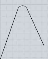
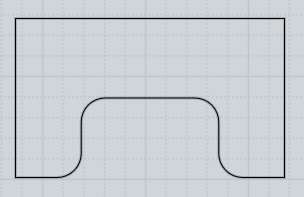
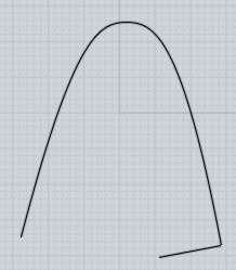
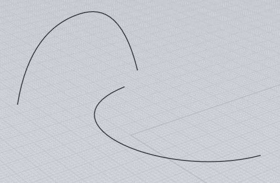
Areas with tight bends in them can also limit the maximum possible fillet size. Here is an example
to demonstrate - imagine that the bent curve corresponds to a tightly curved area of
a model, and the line represents a fillet radius that is larger than the size of the bend.
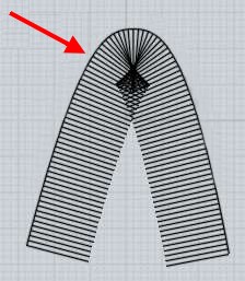
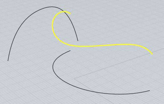
As the filleter travels along the curve, it will try to maintain this distance, but you can see
how this will cause a pinched and bunched up area around the tight bend where the lines are not
cleanly separated and intersect with each other. The same kind of self-intersecting and bunching
would happen to a fillet surface that tried to maintain a large radius as it goes through a tight bend.
If you want to place larger fillets on your model you usually need to avoid making very tightly
bent areas like this:
Normally fillets on a solid are applied to edges of the model. An alternative filleting mechanism
is available by selecting 2 individual unjoined surfaces and running Fillet (you can use Edit/Separate
to break a joined model up into individual separate surfaces). This style of surface/surface
fillet is created by processing just the 2 surfaces instead of making the fillet try to follow
edges, so it can succeed in places where the edge-based fillet will fail. This can sometimes be used
to create fillets one piece at a time in difficult areas. The tradeoff is that these fillets will
tend to require more manual trimming where pieces meet up while the edge-based filleting
automatically trims and handles corner areas.
A variable radius fillet can be performed where the fillet radius changes at certain spots along the edges like this:

You can use variable radius fillets by expanding the "Fillet set" section in the fillet options, and adding
in a new point set by picking points on the edges. Once you have defined a point set, the next radius you enter will
control the radius just at those points. You can click on the "Current set" line to pop up a menu to control which set is
currently active and being manipulated by the Radius control, and also to delete prior point sets. There is a demonstration
video for variable radius fillets here: Variable radius demo on YouTube.
 |
| Offset |
 |
| Offset |
Create a new object at a constant distance away from an existing one.
Offset can be used on solids, surfaces, or curves.
Examples of Offset:


Offset tends to be used more often on curves, with the Shell command being used
instead more frequently on solids or surfaces.
For curve offsets, Through Pt mode will let you pick a point and calculate the offset
that passes through that point. Distance mode allows entering a specific offset distance
and then you pick which side of the curve to offset towards by clicking with the mouse.
Offset for surfaces or solids allows you to either pick 2 points to define the offset
by the distance between the points, or enter a specific distance.
 |
| Planar |
Create a planar surface from outline curves, or fill in end caps on planar
openings on surface edges.
Curves that form a closed loop will be turned into a trimmed planar surface. It is possible
to have nested outlines to form holes. Planar will join curves together during its processing,
it is not necessary to run join before it as a separate step.
For surfaces, unattached edges will be examined, and if they form a closed
planar loop a trimmed plane will be created and joined together there.
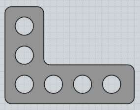
Examples of creating planar surfaces:


 |
| Extrude |
Creates a solid or surface by tracing an outline along a direction.
Extrude works on selected curves or faces. Closed curves may contain
other closed curves inside them to form holes in the final result.
If the automatic assigned direction is not what you want, you can click the
"Set dir" button and click 2 points to define a specific extrusion direction.
Example of extrusion:


Extrude also has a "Set path" option which enables you to pick a path curve
to be used as the extrusion shape instead of the regular straight line path.
The outline and the path curve are combined together to make the output shape. This
is different than sweep since sweep rotates the profile staying perpendicular along
the path while Extrude will not rotate it. Extrude with Set path has the special
property that the output surface will have the exact same control point structure
as the curves used to generate it, so sometimes this can be useful if you want to
set up a surface and manipulate the surface's control points to deform it.
An example of Extrude with a path:


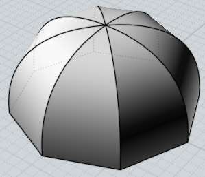
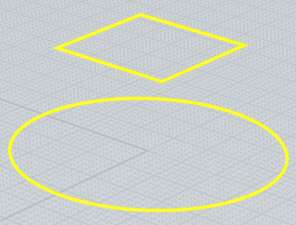
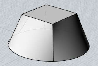
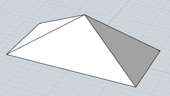
Other options for Extrude include extrude to point which can be useful for making
pyramid or cone-like objects:

For extrude to point, initially the point will track along the same vertical line
through the shape's centroid that the regular extrude also tracks along. If you want to
pick a point away from that line for the tip you can push the "Unlock direction" button
which will then allow you to place the top point anywhere.
The "Tapered" option allows you to produce an extrusion with a draft angle applied to make the side walls
at a specific angled slope. You can also have interior outlines which will flare in the
opposite direction. The height of the tapered extrusion will generally be limited to be less than
whatever amount would cause different sides of the profiles to collide into one another:
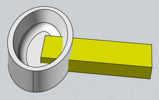
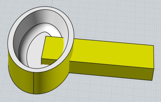
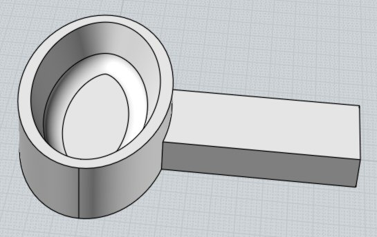
If you select a face sub-object of a solid as the input for extrude, the result of the extrusion
will get automatically booleaned with the base object, allowing for a "push/pull" type action on solids.
Extruding the face in an outward direction makes a Boolean Union of the results, while going inwards
does a Boolean Difference. See here for an animated example of face extrusions with auto booleans:
Face extrusion forum post.
 |
| Revolve |
 |
| Sweep |
Creates a solid or surface passing through cross-section profiles, guided by one or two rail path curves.
Select the profiles first, then run Sweep and select the rails next.
Sweep has different options and behavior depending on whether you use one or two rails. Selecting 3 or more rails
will be treated as a batch operation performing a one-rail sweep along each rail.
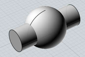
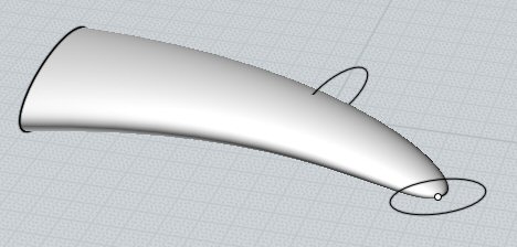
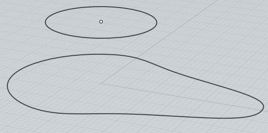
One rail sweep:
Sweep using one rail will trace the profiles as they move along the rail, staying
perpendicular to the rail as they slide along it. It is the main tool for making tubular
type shapes. Profiles may be either placed directly along the rail, or you may place the profiles
all flat on a plane away from the rail and MoI will automatically move and rotate the profiles
into place along the rail for you. To enable auto-place mode make sure the profiles are positioned
outside of the bounding box around the rail curve. Multiple profiles may be used in auto-place
mode by placing the profiles in a left to right order.
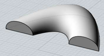
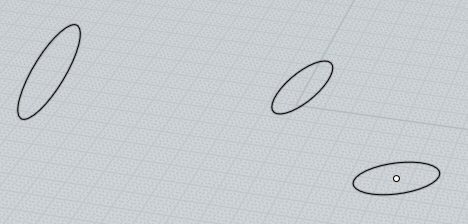
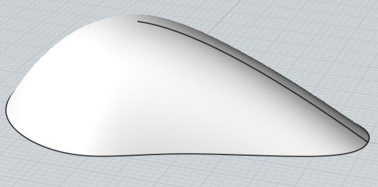
Example of sweep with one rail:

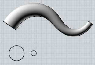
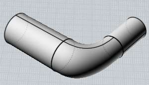
If the rail has sharp corners in it, and there is only one profile curve,
the resulting sweep will be mitered at the corner areas:


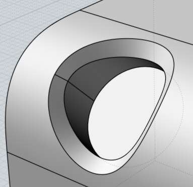
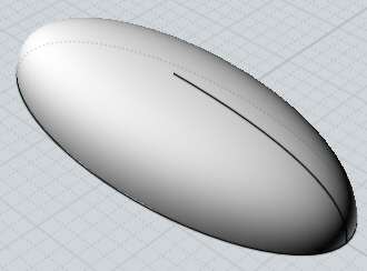
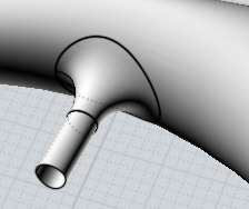
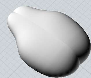
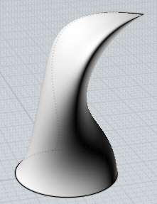
You can use the Ends: option to make a one-rail sweep collapse to a single point at
the start or end to make a tentacle type shape.
By default, a one-rail sweep will gradually rotate the profile as it travels along the
rail curve. This works well for paths that loop all over in 3D, but you can change the
Twist: option to Twist:Flat to only allow rotations in the world Z axis direction, which
keeps the profiles stabilized with respect to the ground x/y plane. When Twist:Flat is set,
an additional "Set flat direction" button will show up in the command options, which
you can push to pick 2 points to define which direction to use instead of the default
Z axis direction. Twist:Freeform is the default
since it works on any shape of path, while Flat does not work on paths that have a tangent
in them that goes straight upwards in Z. In this example the
second image has Freeform twist, and the last one has Flat twist:


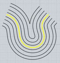
The scaling rail option allows you to pick an additional rail curve which will deform the
sweep. The profiles from the original sweep will be scaled up to match up with the scaling rail.
In a sense it provides a way to control the length-wise profile of the sweep. When a scaling rail
is active, the "Maintain height" option can be used to control whether the scaling will be applied
only in one direction towards the rail resulting in a kind of stretching effect, or whether the
profile will be scaled in all directions uniformly. A scaling rail allows you to
further refine the shape of the sweep using just one curve that can be more easily
controlled than using a large number of cross-sections. The scaling rail should cover
the full extent of the sweep, with each profile being able to extend perpendicular to touch it.
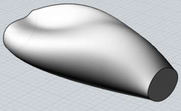
An example of using a scaling rail, shown first with the regular sweep then with the scaling rail active:


Two rail sweep:
Sweep with two rails traces one or more profiles as they slide along 2 guide
rails on either side of the profiles. The profiles can either be positioned
directly on the rails, or same as one-rail sweep the profiles can also be
positioned flat on a plane away from the rails (outside the bounding box
around the rails), and they will be automatically positioned. An example
of two rail sweep:


When the "Maintain height" option is enabled, the profiles will stretch just in
one direction to fit between the rails. When it is disabled, the profiles will scale
in all directions uniformly when they are fit between the rails.
The scaling rail option works similar to one-rail sweep, it allows you to pick
an additional rail curve to stretch the profiles up to. In this case the scaling
rail should generally run down the middle between the 2 rails. An example of
two-rail sweep with a scaling rail:


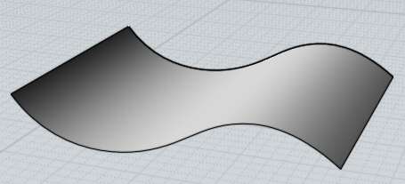
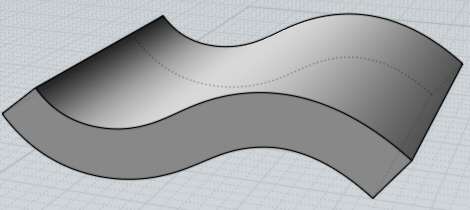
The Maintain tangent option can be used in certain situations to make a sweep
that will mirror without a crease. Consider this sweep and the result after mirroring it:

The reason for the creasing is that the different shaped rails cause some twisting
of the profile shape as it slides along them at slightly different distances.
Preserve tangent mode can be activated in situations like this to prevent this
kind of twisting. To enable preserve tangent mode, all the profiles must share
a common tangent direction along one rail, and they all must be parallel planar
shapes. This mode slides the profiles along keeping them in the same plane. Here
is the previous example swept with Preserve tangent active and then mirrored:

Both one-rail and two-rail sweep also combine profiles together into one
common structure similar to Loft. See Loft above for details on the Profiles
option.
 |
| Network |
Creates a surface from a 2-directional network of curves.
To create a network surface, select all the curves that make up
the network before running the command.
The curves that make up the network should form a kind of 2-directional
grid, similar to a fishing net. A network surface is sort of like doing a loft in 2 directions simultaneously.
MoI needs to be able to organize the curves into 2 different sets for this command to work.
It is not necessary for the curves to exactly intersect, but they should
come close to each other since that helps MoI detect the organization and separate
them into 2 different sets. The network can be closed in either direction and can
also come to a point.
You can also use Network to create a surface from 3 or 4 curves that touch
end to end in a loop, sometimes this is referred to as a "Coons patch".
The "Mode" option can be adjusted to modify the fitting behavior.
You can use one of the other modes than "Normal" if you want to output a less constrained
and lighter surface at the expense of it not hugging as tightly to the boundary curves.
Mode = "Normal" fits the boundary curves by the regular fitting tolerance.
This makes the resulting surface hug the shape of the boundary curves accurately
enough so that it can be joined to other surfaces built off of those same curves.
Mode = "Lighter" makes the surface fit to a looser tolerance, making a lighter surface
but that adheres less to the boundary curves.
Mode = "Custom" - allows you to enter in a numeric tolerance value of your own choosing.
Mode = "Uniform" - allows you to enter in a number of points - each section of the Network
is fit with that fixed number of control points per region rather than refining things adaptively
to meet a distance tolerance like the other modes.
Mode = "Exact" - enabled for 3 or 4 sided networks only. This mode makes a Coons path
with no refitting of the input curves. The surface's edges will exactly coincide with the input
curves but if the curves have uneven parameterization the surface can tend to be awkwardly
bunched in places.
Some examples of network surface:


 |
| Curve |
|
| Project |
Projects a curve on to a surface or solid.
First select the curve, then run Project and then select the surface or solids
that will receive the curve. A default direction will be used, and you can pick 2
points to define a different projection direction.
Example of curve projection:


 |
| Isect |
Creates curves or points at intersections between objects.
Select all the objects to be intersected before running the command.
Curves will be created at the intersections between 2 surfaces or solids,
and points will be created at the intersections between a curve and other objects.
Unlike the Booleans, this does not modify the objects, it just creates new curve or point objects.
This command can also be used to create a "curve from 2 views" when the inputs
are 2 planar profile curves facing different directions. This is the equivalent
of doing an extrusion of each curve and intersecting the extruded surfaces.
So for example with these 2 curves one of which was drawn in the Top view
and one in the Front view:
You can select both of those curves, and run Construct / Curve / Isect to
generate this result curve:
 |
| Silhou |
Creates silhouette curves that give the profile of a curved
surface from a particular view.
This can be useful to run before exporting to AI format -
set up your view how you want it, then run Silhouette to generate
the outline curves, then immediately export all of that to AI format.
Make sure not to rotate or zoom your view in between generating the
silhouettes and exporting because the silhouettes are tied to
a particular viewpoint when they are done in the 3D view.
The "Include edges" option controls whether to include trim edges
that are silhouettes (for example the edges on a box) in the results
in addition to curved surface silhouette calculations.
For example given this model:

Running Silhouette on it will generate these result curves:

 |
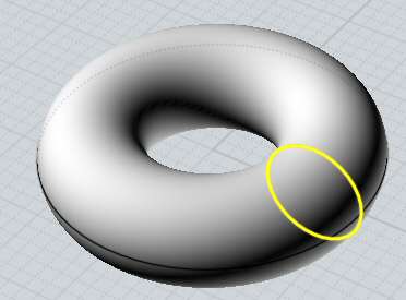
| Iso |
Creates an Isocurve going through a point on a surface. An Isocurve is a curve on a surface
that runs along the surface's own U or V directions. They can be convenient for some operations
since they follow the natural rectangular layout of a surface.
On several types of primitives isocurves will be key features of the object like for example
on a sphere one isocurve direction will be a circle of latitude on the sphere and the other
direction will be an arc of longitude on it.
Example of Isocurves:

Back to reference index Prev page Next page
© 2014 Triple Squid Software Design