Back to reference index    Prev page    Next page

Transform
Move

Moves objects by the displacement between 2 points.

Generally most object movement is done by directly dragging on an object while not inside of any command, instead of using this command. However, the Move command is provided so that it is possible to do precision movement using any 2 snapped points. Here is an example of moving a circle so it is centered about the origin. This is done by snapping the base point to the center of the circle and the target point to the origin.

This would be more difficult to do with the quick dragging method since dragging is activated by clicking directly on the object, so it is not possible to grab the center point of a circle as the base point when dragging.

When picking the target point the "Distance from edge" option can be clicked and a distance specified, which will then place the target point at that distance away from any line that is snapped on to.


Copy

Create copies of an object, placed at specific points.

Copy works similar to Move, but allows you to click multiple target points and drops a copy of the objects at each one.

Use Edit/Copy and Edit/Paste instead if you want to create a duplicate of an object in its exact same location.


Rotate
Rotate

Rotates objects around a center point.

To rotate objects, first select the objects and then run the Rotate command. Next pick a center point for the rotation. After you have picked the center of rotation you can then either type in a number for the angle to rotate by, or you can use the mouse to pick an angle. To use the mouse you pick 2 additional points that act as arms or handles coming out from the center point. The angle between these 2 arms will be the angle of rotation. The angle is specified using these 2 clicks so that it is possible to snap on to existing objects to calculate a precise rotation.

Example of rotating a rectangle 90 degrees using the mouse:

After selecting the rectangle and running Rotate, pick the center point for the rotation, in this case the center of the rectangle:

Next, the first angle reference point is placed off to the right snapped to the x axis. This sets the starting point for the angle:

Finally, the second angle reference point is placed off to the top snapped on to the y axis. This sets the ending point for the angle. The object will rotate by the angle between the 2 reference lines:

Here's an example showing how the points can be snapped to calculate a precise rotation relative to existing objects, in this case snapping on to the corners of the rectangle, with the center of rotation off to the left side:

You can check the "Make copies" button or hold down the Ctrl key when clicking the last point to drop rotated copies of the object.


Rotate Axis

Rotates objects around an axis line.

The regular Rotate command operates in a 2D fashion relative to the grid. Rotate axis allows you to pick 2 points to define an axis line to rotate around. It can be used to rotate around an arbitrary direction that is not aligned with any grid.

The operation is similar to 2D rotate, except instead of a center point you pick 2 points to make an axis line. Then you can enter a numeric angle to rotate by, or use the mouse in the same way as 2D rotate, with 2 reference arms tracking out from the first point of the axis.

An example of rotating a polygon up 30 degrees from the x/y plane around one of its own edges:

After selecting the polygon and running Rotate Axis, the first axis point is picked at one corner of the polygon:

The second axis point is picked at the other end of the polygon's edge:

Then 30 was entered for the angle, resulting in the polygon rotating up from the x/y plane by 30 degrees:

The rotation axis works as kind of a hinge and the objects pivot around that hinge.

You can check the "Make copies" button or hold down the Ctrl key when clicking the last point to drop rotated copies of the object.


Scale
Scale

Scales objects around a center point.

This type of scaling is sometimes called a "Uniform" or "3D" scale since it scales equally in all axis directions.

To scale objects, first select the objects then run the Scale command. Next pick an origin point for the scale. This will be the fixed point which the objects will scale around. After you have picked the origin for the scale you can then either type in a number for the scale factor, or you can use the mouse to pick a scale factor.

When entering in a number for the scale factor, 1 represents no scaling. So for example:
2 will double the size of the object,
0.5 will shrink the object to one-half the original size,
10 will increase size by 10 times,
0.1 will shrink the object to one-tenth the original size,
etc...

You can set the scale factor using the mouse by picking 2 additional reference points. The relative distances of these points from the scale origin determines the scale factor. For example, if the second point is twice as far away from the origin as the first point, the scale factor will be 2.0 .

Example of scaling a rectangle using the mouse to set the scale factor:

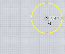
After selecting the rectangle and running Scale, pick the center point for the scale, in this case the corner of the rectangle:

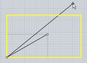
Next pick the first reference point. In a certain sense this point will calibrate the scale and set the distance that will correspond to a scale factor of 1. In this case the opposite corner of the rectangle was picked. Often times the first reference point may be snapped on to the perimeter of the object away from the scale origin:

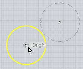
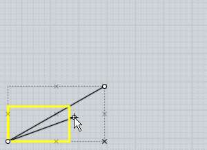
Then the final reference point determines the scale factor, comparing its distance with the first distance. If you move the second reference point further away from the scale origin than the first reference point, the object will become larger:

If you move the second reference point closer to the scale origin than the first reference point, the object will become smaller:

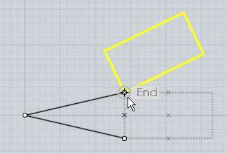
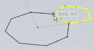
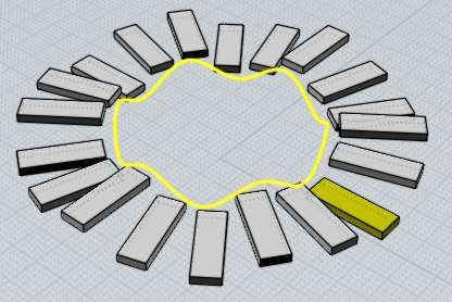
Scale works with reference points in this way to make it possible to snap points on to strategic areas to calculate scaling measured to existing objects. For example, say you want to scale up a rectangle by just the exact right amount so that it would touch an object above it. This is possible by careful picking of the reference points to measure the existing distance, and then the desired new distance. The proper scale factor for converting the existing distance into the desired distance will be calculated and applied to scale the object:

You can check the "Make copies" button or hold down the Ctrl key when clicking the last point to drop scaled copies of the object.


Scale 2D

Scales objects around a center point, stretching them just in 2 axis directions.

Scale 2D works similar to Scale except the scaling is not applied in all directions, it is only applied in one 2D plane. The plane used depends on which viewport the origin point is picked in, so you will get a different effect if you pick in the Top view versus the Front view for example. The directions used correspond to the x and y axes of the viewport's grid.

See regular Scale for details on how the reference points work.

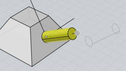
Example of scaling a cylinder with Scale 2D. The cylinder is widened in the x/y plane, but its height remains fixed:


Scale 1D

Scales objects along a single direction.

Scale 1D is similar to scale, except the scaling is only applied in one direction. The direction is defined by the line between the origin and the first reference point.

See regular Scale for details on how the reference points work.

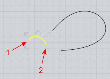
Example of scaling a circle into an ellipse along a diagonal:

Scale 1D can be used to stretch or compress an object to a new height while leaving its shape unchanged in X and Y. For example, here a piece is stretched in z by picking the scale origin at the bottom of the piece, the first reference at the top of the piece directly above scale origin (this forms a line going along the z axis which will be used as the scaling direction), and then the final reference point at the new height above it.

In the previous example, picking the final point lower than the first reference point would result in the piece squishing down to be shorter instead.


Mirror

Creates a mirrored copy of an object around a dividing line.

To mirror an object, select it then run the Mirror command. Next 2 points are picked to define the axis that the object will be reflected around.

The new mirrored object has history updates enabled by default so the mirrored version will update when you edit the original.


Array
Grid

Duplicates objects in a rectangular or cube layout.

To create a grid of duplicated objects, select the objects to duplicate and run the Array Grid command. At the "Choose number of copies" prompt, enter the number of elements to use for the grid in x, y, and z and click Done. Then the final stage is for entering the spacing that will be used between each element of the grid. This can either be typed in, or you can draw a rectangle or box around one element to define it.

Here is an example of drawing the spacing with the mouse and the result (result shown zoomed out):


Dir

Duplicates objects along one direction.

To create a duplicated column of objects, select the objects to duplicate and run the Array Dir command.

The Mode: option controls the spacing behavior.

With "Mode: Offset, Count", the "Item count" option controls how many copies will be made, and you pick 2 points to define both the direction and the spacing between the copies.

With "Mode: Extent, Count", you also give an item count and 2 points, but the distance between the points is taken as the full extent, with the offset distance between copies being calculated as a distribution to fit inside of that.

With "Mode: Offset, Extent", you instead pick 2 distances and the item count is calculated for you and displayed in the options panel. Either start with the small distance as the offset, and then move your mouse further for the second distance to create as many copies as will fit within that longer distance, or start with the long distance first and move your mouse closer to the base point to reduce the offset and generate more copies within that extent.

Example of Array Dir with Mode: Offset, Count. In this case a 5-sided polygon is being duplicated. The first point was placed in the lower-left corner, and the second point was placed in the opposite corner as indicated. The distance and direction between these 2 points defines the placement of the duplicates:


Circular

Duplicates objects in a circular pattern around a center point.

To duplicate objects in a circular pattern, select the objects to duplicate and run the Array Circular command. Next, pick the center point for the pattern, and finally different options for item count and angle can be adjusted.

You can click on the "Angle to fill" label with the small arrow on it to switch between specifying the angle for the full pattern, or the angle for just one single step.

The vertical and radial step options allow you to specify a distance to move each item for every step in the pattern. Vertical controls up and down movement, and radial controls movement away from or in towards the center point. This can be used to create spiral type patterns. Here is an example that used an Item count of 50, Angle to fill of 900 degrees, Vertical step of 1 to move upwards one unit for each step, and Radial step of -0.3, to slide a small distance in towards the center on every step:


Curve

Duplicates objects along a path curve.

To duplicate objects along a path curve, select the objects to duplicate, then run the Array Curve command. Next, select the path curve. Finally, you can adjust options for spacing and rotation and click Done when you are finished.

You can enter either the number of items you want to have along the path, or the distance between items. If you enter in a total number of items, the distance will be calculated for you. If you enter in a distance, the number of items that fit along the path using that distance will be calculated for you.

There are different options for controlling the orientation of the objects as they travel along the path.

Rotation:Freeform calculates a change in orientation by doing a gradual rotation around the curve tangent. This means that there isn't any abrupt change at any one point, but the orientation will be constantly changing and in some cases can end up upside-down.

Rotation:Flat will only do rotations about the world Z axis. It will swing the object around the z axis to point it as much as possible in the tangent direction of the curve, but it will always stay pointing upwards, giving it a kind of stabilizing effect with regard to the z axis. This can work well for simple path curves, but it doesn't work well if the path curve slopes upwards very sharply with any parts tangent or nearly tangent to the z axis.

Rotation:None performs no orientation of the object at all and just moves it along the path curve.

Example of duplicating along a path curve. In this case the object to be duplicated is a box and the path curve is a circle that has been edited to have a wavy shape:

Rotation:Freeform produces this result:

Rotation:Flat produces this:

Rotation:None produces this:


Align

Lines up control points or objects along a straight edge.

To align objects, select the objects or points to modify and run the Align command. You can then adjust the options for performing either a vertical or horizontal alignment and how objects will stack up against the alignment edge (like along the tops or bottoms of the objects or through the center, etc...). To finish the alignment, pick a point to define the location of the alignment edge.

Example of using align to center objects along a horizontal edge through the center of a rectangle:

Another use for Align is to adjust the 2 control points at the end of a curve to be exactly horizontal or vertical with each other. The 2 points at the end of a curve control the ending tangent direction of the curve, and if the end tangent is lined up it will allow for mirroring the curve without any sharp crease between the mirrored copies.

An example of aligning control points in preparation for mirroring around the vertical axis. This curve had points turned on by Edit/Show pts. The points are not aligned horizontally - if this curve is mirrored now there will be a sharp corner between the mirrored copies. To fix this, select the 2 points:

Next, set the alignment option for "Horizontal center", and then pick the point to define the alignment edge, in this case picking the end point will define the alignment edge through the end point:

This results in the 2 points being lined up with one another and now the curve can be mirrored without a sharp crease forming:


Orient
Orient

Positions and rotates objects from a base frame to a target frame, with a focus on positioning objects relative to one another.

Orient can be used to match a planar face on one object to coincide with another plane on a different object, or to map an object to a surface normal on a curved surface.

Here is an example where a cylinder is being reoriented to match the side of a pyramid:

To use Orient you pick a base orientation, and then a target orientation, and the selected objects will be mapped from the base to the target. In the example above, the base orientation was picked at the center of the cylinder's cap and the target orientation was picked on the sloped pyramid side.

Each orientation pick consists of 2 steps. The first step is to place the origin point. If the origin point is snapped on to an object the x/y/z axis directions will be initialized to be aligned to that object, unless you disable the "Align to objects" option. After the origin point is placed, the second step is to optionally adjust the axis directions by dragging on an axis line to alter where it points towards. Press the "Done" button or right click in a viewport when the axis directions are configured how you want.

For simple placements where you don't need to adjust the rotation you will do 4 clicks total: 1 click to pick the base origin point, 1 right-click to accept the default rotation, 1 click to pick the target origin point, and 1 more right-click to accept the default target rotation.

Also see Orientation picker for some more details.

You can enable the "Make copies" option or hold down the Ctrl key when clicking the target origin point to drop copies of the selected objects and keep the original in place.


Line/Line

Transforms objects from a base line to a target line.

First 2 points are picked to define the base line, often times these points will be snapped on to the ends of a curve that is being transformed. Then 2 more points are picked to define the target line.

The objects are moved, rotated, and also optionally scaled to match the first line to the second.

The Scaling option allows for scaling to be disabled, or for scaling to happen by stretching in one direction only instead of uniformly.

You can enable the "Make copies" option or hold down the Ctrl key when clicking the target line to drop copies and keep the original objects in place.

Here's an example where a curve is being transformed so that its ends coincide with another curve's endpoints:


View/View

Remaps objects from one view to another view.

You control which views are used by clicking inside of them, first do one click inside the source viewport (anywhere in it, it doesn't matter on which specific point), and then click once in the target viewport.

So for example if you have imported some 2D curves that are flat in the Top view, you can use this command to quickly shift them to be flat in the Front view instead, same as rotation by 90 degrees but without needing to do the rotation in some other side view.

You can also click in the 3D view as either a source or target view which will use the camera's view direction for the orientation.


Back to reference index    Prev page    Next page


© 2010 Triple Squid Software Design