Back to reference index Prev page
Misc
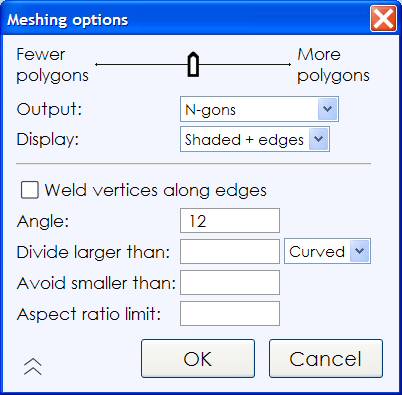
When saving to a polygon file format, MoI needs to convert from smooth surface data into faceted polygon data. The "Meshing options" dialog is shown during this process to control different aspects of how the polygon data is generated.
During the meshing process the number of generated polygons and points are displayed in the upper-right corner of the main window where command options normally are shown.
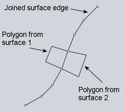
MoI does extra work to align mesh vertices along shared edges between joined surfaces. So you'll generally want to make sure surfaces that are next to one another have been joined together into one connected solid object before exporting mesh data.
Initially the dialog is shown in its compact form:

Move the slider to the left to create a lighter mesh with fewer polygons. This will reduce the amount of data generated but will also give a more jagged appearance to the mesh. Move the slider to the right to create a denser mesh with more polygons in it. A denser mesh will be smoother visually but will also contain a lot more data.
The Output: option controls the type of polygon data that will be created, whether to allow creation of N-gons (polygons with more than 3 or 4 sides), or whether to break polygons up to only allow 3 or 4 sided polygons. Some programs have difficulty dealing with complex N-gon shapes. If you see bad results when importing N-gons into your polygon application, try reducing this option to Quads & Triangles, or Triangles only. Some polygon file formats don't allow N-gons, for example STL or 3DS files can only contain triangles, so you won't see this option when exporting to these formats.
You can click on the arrow in the lower-left corner of the compact dialog to expand it to show more options:
Weld vertices along edges option:
Welding controls how polygons are connected to points along shared edges between surfaces. When welding is on, polygons will share a single point in common along the shared edge. When welding is off, the polygons on each side of the edge will have their own individual points which are stacked up in the same location.
Example of welded polygons - each polygon from either side of a joined edge will be hooked into the same vertex. The vertices are shared between polygons:
Example of unwelded polygons - in this case each polygon across the unwelded edge has its own individual vertices. The points are stacked on top of each other, shown slightly separated here for illustration: 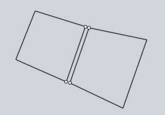
Typically welding is left on for normal rendering use but some programs may have difficulties with welded meshes. Also, sometimes you may want to have points unwelded for certain special effects, such as doing a sketch or toon style rendering. Unwelded edges will get an accent line in a sketch rendering. Turning welding off may also help separate polygons out into different chunks for each original surface during later polygon editing.
Angle option:
The Angle option controls the maximum angle allowed between the surface normals at the corners of each polygon. When the maximum allowed angle is small, it will force additional subdivisions along more tightly curved areas. When the maximum angle is larger, fewer subdivisions will be forced in curved areas and coarser polygons will be allowed. This is the same value that is controlled by the slider. This option just allows you to control it more directly and to allow for values outside of the normal slider range. For example, if you want a very low polygon mesh you may want to type in a larger angle here than the slider normally permits.
Divide larger than option:
The "Divide larger than" option provides another way to refine the mesh in certain areas. You can enter a distance here which will force polygons that are larger than this length to be broken down into smaller pieces. This can be used to add detail to larger areas that have shallow curvature. Areas that have shallow curvature will tend to get fewer polygons in them because the regular density control that is adjusted by the slider is based only on curvature and not lengths. You can also adjust the drop-down to limit additional subdivisions to a specific type of surface. By default it will be applied only to curved surfaces leaving planar surfaces unaffected, but this can be changed to only apply to planar surfaces for special meshing needs, or to apply to all surfaces.
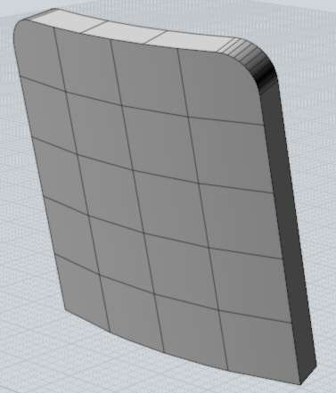
Here is an example of a large area with shallow curvature that didn't get many polygons. Because it is covering a larger area the lack of refinement here can be more noticeable:

By entering a distance of 5 in the "Divide larger than" option, it will force more divisions along the large shallowly curved surface. Any polygon larger than 5 units along an edge will be further broken down:
Avoid smaller than option:
The "Avoid smaller than" option can be used to avoid creating too many polygons in small areas where they may be difficult to see, in order to reduce polygon counts. You enter a distance here, and subdivisions will be restricted for any polygon that is smaller than this value. Normally the same density will be generated in both small and large areas because it is controlled only by the curvature. This is good if you are going to be zooming into a smaller area for a rendering, but if you're never going to zoom in to a small area you may wish to have fewer polygons there to reduce the amount of data being processed and speed things up.
Here's an example of a knob that is a tiny piece of a much larger model:

By setting an "Avoid smaller than" distance of 0.5, it will reduce the number of divisions there since this knob is close to that size:

Aspect ratio limit option:
The "Aspect ratio limit" option offers another way to force additional subdivisions for quads that are short in one direction but long in another. This affects all surfaces, including planar ones. Here is an example of a mesh with long and skinny quads:

If you want to get more regularly sized quads here, you can enter 2 in the aspect ratio control, which will force a division in any quad that has one edge more than twice as long as the other:
Once you enter a value into one of the extended controls, you can clear it by either using backspace to clear the field or by entering a value of 0.
You can repeat the most recently used command by right-clicking inside a viewport or by pushing the Enter key on the keyboard.
It is also possible to turn on repeat automatically for a period of time by clicking the "Repeat" checkbox that shows up at the bottom of the command options area in the upper-right area of the window. When that option is checked, a drawing command will automatically repeat until you cancel it or uncheck that box.
Construction lines allow you to quickly place additional guide lines to help with precise snapping and alignment while drawing shapes.
You can create a construction line anytime that MoI is asking you to specify a point location, like for the start or end of a line, the center of a circle, the next point of a curve, etc... To create a construction line, hold down and drag the mouse.
When MoI is asking you for a point, clicking and releasing the mouse button will finish picking that point. If you hold the button down and drag instead of releasing, you will drag out a construction line. Construction lines are automatically erased at the end of each command.
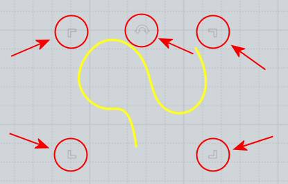
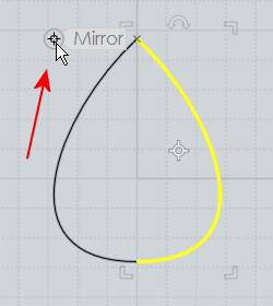
Here is an example of how a construction line can be used to help accurately place a point. Imagine you have a drawing as shown here in the first image, and you want to create a new horizontal line as shown in yellow in the second image, such that the end is exactly aligned as indicated by the dashed line:

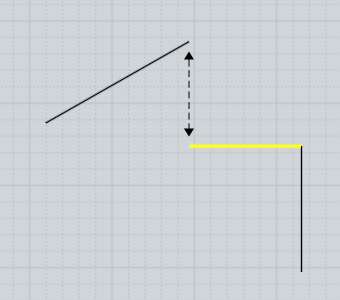
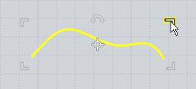
To draw such a line, start the line command and click the first point at the end that you can easily grab:
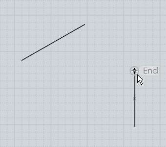
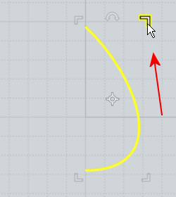
Next, move to the end that you want to be aligned with. Click down on that point, but do not release the mouse button. Instead hold the button down and drag away and a construction line will be created. Drag downward to make the construction line go downward, and release the mouse when you see the construction line has snapped vertically:
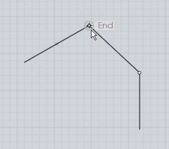

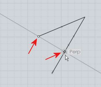
Now that a construction line has been created dropping down from that point, you can find a snap point at the intersection between the horizontal line and the vertical construction line, and click it to place the end of the line:

You can drag out any number of these construction lines to set up additional intersection snaps. They can be dragged along the x, y, or z axes, perpendicular or tangent from a curve, etc... The construction line is formed through 2 points - the point you started the drag on and then the point where you release the mouse. After a construction line has been defined by these 2 points, the midpoint between them is available as another snap as well as the reflected endpoints. The reflected endpoints are calculated by taking the distance between the start and end and repeating that same distance in both directions. For example, creating a construction line through the 2 points in the first image will provide the additional snaps shown in the second image:

This makes it possible to find the midpoint between any 2 points by dragging a construction line through those 2 points. Also the reflected endpoints can be useful for snapping symmetrically around a centerline.
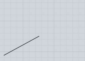
Here is an example of how the reflected endpoints can be useful. Let's say you have a line, and you want to draw a square at the end of the line, centered around it, like so:

To do this, start the Rectangle 3 points command. Before placing any points for the rectangle, go to the end of the line and drag out a construction line perpendicular to it:

Thanks to the reflected endpoints, this now sets up all the snaps you need to draw the square. Place the first point at the original end of the construction line, point #2 marked above. Then for the next point of the rectangle, pick the reflected endpoint on the other side:

Finally, the square snap built into the rectangle tool can be used for placing the 3rd point to form an exact square:

Construction lines can be used in this manner to form a kind of quick temporary scaffolding or grid adapted to the size and orientation of existing objects.
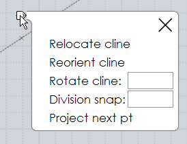
After you drag out a construction line, a small marker will appear above your mouse pointer that looks like this:

If you move your mouse over that marker the marker will brighten up and if you press and hold down on the marker for a moment a menu will pop up with additional options for controlling the construction line:
The "Relocate cline" option allows you to pick a new point for the construction line to go through, basically dragging the construction line to a new location. This allows you to capture a direction and then move it to a different area to use for a parallel construction guide.
The "Reorient cline" option allows you to pick a new point and pivot the construction line to point in a new direction going through that point. The original endpoints, midpoint, and reflected endpoints of the construction line are still available as snaps at the same distances after the reorientation. This, combined with the relocation option, allows you to use a construction line as a kind of measuring stick to capture a distance between any 2 snapped points and then apply that distance to a different area or different direction.
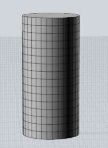
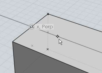
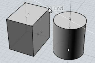
Here is one example of measuring a distance and applying it in a different direction while drawing a cylinder on top of a box. After starting the cylinder command, a construction line is created from the midpoint of the box's edge to the end:
Then the construction line is re-oriented to point perpendicular to the edge, towards the inside of the box:
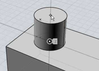
Now there are snap points available at the same spacing as the edge of the box to draw an exactly placed cylinder:

The "Rotate cline" option allows you to rotate the construction line around its base point by the given angle. This allows you to set up a guide line at the given angle relative to some existing edge of an object. It is also possible to use Distance or Angle constraint while initially drawing the construction line by dragging outside the viewport to the distance or angle controls and clicking and entering a constraint value there, then returning to the viewport and clicking to place the second point of the construction line.
The "Division snap" option enables you to snap to different fractional increments along the construction line instead of only the midpoint. For example, entering 5 here will provide snaps at 1/5, 2/5, 3/5, 4/5, as well as -1/5, -2/5, 6/5, 7/5, etc...
The "Project next pt" option forces the next picked point to be projected to the closest point along the construction line. This allows you to snap on to a different object and find the relative height of that point along the line. For example, here a construction line has been pulled up in z along side of a different object. When projection is turned on you can move to a snap point on the other object and the relative height of that object will be captured by the projection on to the line:
Here is an example of this projection being used to place the top point of a cylinder at an equal height as an existing box object:
Keys or key combinations can be assigned to different actions under Options / Shortcut keys.
The Enter and Esc keys have predefined functions. You can use Enter as a shortcut for clicking the "Done" button while inside of a command, and pressing it outside of a command will repeat the last used command. Esc is used to cancel or turn off modes. If you are currently running a command, Esc will cancel the command same as clicking the "Cancel" button. If you are outside of a command, Esc will deselect objects on the first tap, and then turn off any points that were enabled with the "Show pts" command on the next tap.
To create a new shortcut key, click the "Add" button and then fill in the entries for Key and Command.
The key can be defined using a letter (like "A") or one of these labels: F1 - F12, UpArrow, DownArrow, LeftArrow, RightArrow, Home, End, PageUp, PageDown, Insert, Delete, Backspace, Space. The key can be prefixed by one or more of these modifiers: Ctrl+ , Shift+, or Alt+ .
Examples of some key assignments:
| A |
= push the A key with no other modifier keys. |
| Ctrl+A |
= hold down Ctrl and push A |
| Ctrl+Shift+A |
= hold down both Ctrl and Shift and push A. |
| Ctrl+UpArrow |
= hold down Ctrl and push the Up arrow. |
The Command can be filled in with either the name of a command, or a script macro. Script macros are prefixed with the keyword "script:".
Command names:
AddPoint, Align, Arc3pt, ArcCenter, ArcContinue, ArcTangent, ArrayCircular, ArrayCurve, ArrayDir, ArrayGem, ArrayGrid, Blend, BooleanDifference, BooleanIntersection, BooleanMerge, BooleanUnion, BoundingBox, BoundingBoxCenter, Box, Box3pts, BoxCenter, Chamfer, Circle, Circle3pt, CircleDiameter, CircleTangent, Cone, Conic, Copy, CopyClipboard, CopyClipboardWithOrigin, Curve, Cut, Cylinder, Delete, Ellipse, EllipseCorner, EllipseDiameter, ExplodeMove, Export, Extend, Extrude, Fillet, Flip, Helix, History, Image, Import, ImportPart, IncrementalSave, Inset, InterpCurve, Intersect, Join, Line, Loft, Merge, Mirror, Move, Network, New, Offset, Open, OpenTemplate, Orient, OrientLinetoLine, Paste, PastePart, PlanarSrf, Plane, Plane3pts, PlaneCenter, Point, Polygon, PolygonEdge, PolygonStar, Polyline, Project, RailRevolve, Rebuild, Rect3pts, Rectangle, RectCenter, Revolve, Rotate, RotateAxis, Save, SaveAs, Scale, Scale1D, Scale2D, Separate, Shell, ShowPoints, ShrinkTrimmedSrf, Silhouette, SketchCurve, Sphere, Sweep, Text, Trim
So for example, a shortcut for E to activate extrude would look like this:
E Extrude
There are a few buttons in the UI that run script macros instead of commands: Hide, Reset all, Select all, Deselect all, and Invert. This is so they can be used while a command is still running, so these functions are slightly different than a regular command. To hook these up to a shortcut key fill in the Command part with one of the following scripts:
Hide:
script:moi.geometryDatabase.hide();
Lock:
script:moi.geometryDatabase.lock();
Reset all views:
script:moi.view.resetAll();
Select all:
script:moi.geometryDatabase.selectAll();
Deselect all:
script:moi.geometryDatabase.deselectAll();
Invert selection:
script:moi.geometryDatabase.invertSelection();
Here are some frequently requested scripts that can be assigned to a key to perform a custom action. To use these, copy the entire line that begins with script: and paste it into the Command part of the shortcut key:
Maximize the view the mouse is over, or switch back to split view (usually assigned to Space key):
script:if ( moi.ui.mainWindow.viewpanel.mode != 'split' ) { moi.ui.mainWindow.viewpanel.mode = 'split' } else { var viewport = moi.ui.getViewportUnderMouse(); if ( viewport ) { viewport.viewPanel.mode = viewport.name } }
Go to split view:
script:moi.ui.mainWindow.viewpanel.mode = 'Split';
Maximize the 3D view:
script:moi.ui.mainWindow.viewpanel.mode = '3D';
Maximize the Front view:
script:moi.ui.mainWindow.viewpanel.mode = 'Front';
Maximize the Right view:
script:moi.ui.mainWindow.viewpanel.mode = 'Right';
Isolate the selection (hide everything else that is not selected):
script:moi.geometryDatabase.invertSelection(); moi.geometryDatabase.hide(true);
Select all curve objects:
script:moi.geometryDatabase.getObjects().getCurves().setProperty( 'selected', true );
Select all open curves (curves that do not form a closed loop):
script:var curves = moi.geometryDatabase.getObjects().getCurves(); for ( var i = 0; i < curves.length; ++i ) if ( !curves.item(i).isClosed ) curves.item(i).selected = true;
Hide all curve objects:
script:moi.geometryDatabase.getObjects().getCurves().setProperty( 'hidden', true );
Hide all surface/solid objects:
script:moi.geometryDatabase.getObjects().getBReps().setProperty( 'hidden', true );
Select all objects that were created by the last command:
script:var a = moi.command.lastCommandRevisionStart; var b = moi.command.lastCommandRevisionEnd; var objects = moi.geometryDatabase.getObjects(); for ( var i = 0; i < objects.length; ++i ) { var obj = objects.item(i); if ( obj.databaseRevision > a && obj.databaseRevision <= b ) obj.selected = true; }
Toggle grid snap on or off:
script:moi.drawingAids.gridSnap = !moi.drawingAids.gridSnap;
Toggle object snap on or off:
script:moi.drawingAids.objectSnap = !moi.drawingAids.objectSnap;
Toggle straight snap on or off:
script:moi.drawingAids.straightSnap = !moi.drawingAids.straightSnap;
Many other scripts are possible, see the web site for a larger list, and post any requests for custom scripts to the discussion forum.
The edit frame shows up around the outside of selected objects and allows you to quickly perform scaling or rotation without having to launch any commands.
The edit frame's starting position is based on the bounding box of the selected objects, and is made up of 5 grips - 4 scaling grips in the corners and one rotation grip at the top:
The grips are drawn with a semi-transparent effect to maintain a low profile, but will light up when you move the mouse over top of one.
Primarily the edit frame is intended to be used in the 2D Top/Front/Right views, but it will also show in the 3D view if the selected objects are all planar.
To scale with the edit frame, grab one of the corner grips and drag it to size the object. By default objects will be scaled from the center point, but you can switch to scale from the opposite corner instead by clicking on one of the corners instead of dragging it. Each click will toggle the scaling origin between the center or the corner. When the mouse is over a corner grip, a marker will appear at the current scaling origin.
When scaling, if you drag your mouse in a horizontal or vertical direction, a guideline will appear and the scale will happen as a 1D stretch along that direction. Stay close to this guideline if you want to do a stretch, otherwise if you drag diagonally it will scale the object in all directions. If you move far enough away from the 1D scaling guides, stretch mode will be turned off for that drag. You can also hold down the Shift key when scaling to perform a 2D scale which will stretch only in 2 directions and leave the vertical direction untouched.
While stretching an object, a "Flat" snap is available at the point where the frame collapses completely down to a line. This can be used as a quick way to flatten objects from a side view:

You can also create a mirrored copy of an object using the corner grips as well. To do that, grab a corner and drag it all the way over to the opposite side of the object. There will be a snap point available there and if you snap on to it, a mirrored copy of your object will be produced same as doing the Transform / Mirror command:
Also if you are scaling from the center, there are mirror snap points at the other 3 corners to enable an exact "in-place" type flipping or mirroring.
To rotate with the edit frame, grab and drag the rotation grip which is located in the middle of the top edge of the bounding frame.
You can rotate by a specific angle by entering an angle constraint before dragging the rotation grip. There are 2 ways you can enter an angle constraint, either by typing <angle (like <45) just by typing directly without clicking anywhere, or by clicking on the angle box in the bottom toolbar and entering your value there. So for example if you want to rotate something by 30 degrees, type in <30 and push enter, then grab that rotation grip and it will rotate in 30 degree increments.
If you click instead of drag on the rotation grip, it will switch to a different "wheel mode" which makes it possible to grab the center rotation pivot and move it to whatever spot you would like to rotate around. Also while in this mode there is a tri-wheel rotation widget displayed in the 3D view which allows you to grab any one of 3 rotation axes.
The Properties panel shows up in the upper-right area of the main window and lets you view and edit properties of the currently selected objects.
This panel shows up when you are in Selection mode, before you have launched a command.
In addition to viewing properties, you can also click on different areas to pop up menus or dialogs that allow you to edit them. As you move your mouse over this area you will see different clickable areas highlight.
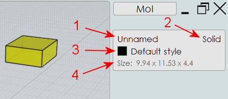
1. Object name indicator - this displays the name of the currently selected objects. You can assign a name by clicking on this line to bring up the "Edit object name" dialog box. Named objects will have entries show up in the Objects section of the Scene Browser to be quickly accessed for hiding, showing, or selecting.
2. Object type indicator - this displays some basic information about the selected object, for example if it is a fully closed solid it will display "Solid" here. The type can be one of the following: Curve, Closed crv, Edge, Face, Surface, Joined srf, Solid, Point. Also if you have multiple objects selected, the number of objects currently selected will be shown here as well.
3. Style indicator - this displays the style that is assigned to the current selection. You can assign a different style by clicking on this line to pop out the styles menu. There is also an alternate way for assigning styles available by clicking on a style's color swatch in the Scene browser. You can right click on this line as a shortcut to edit the style.
4. Size indicator - this displays the bounding dimensions around the current selection, and you can click on it to scale the objects to a different size. The bounding size will be displayed in either world coordinates, or in cplane coordinates if a custom cplane is currently set. Certain objects have special size values - a line will display length, a circle, arc, sphere, or trimmed cylinder will display radius, and a full cylinder or cone will display radius and height.
When editing the size, there is a "Maintain proportions" option you can turn on or off to control whether objects will be scaled uniformly or whether to allow them to stretch in only one direction when a value is edited.
When you enter in a new size, you can enter in numeric formulas (for example: 22 / 5 * 4) and there are also the following variables that be used as part of the formula:
x : bounding x size
y : bounding y size
z : bounding z size
r : radius
d : diameter
h : height of cone or cylinder
l : length of a line
So for example if you want to set a cylinder's height to be twice its current radius you can do that by unchecking "Maintain proportions", and then enter r * 2 into the Height: field.
You can also enter a value starting with + or -- in a field to make it a relative adjustment. For example if you enter in radius: +5 it will add 5 to the current radius.
The scene browser helps to organize larger projects by categorizing objects in different ways and allowing you to perform actions (such as hiding, showing, locking, selecting) to all the objects that belong to a particular category.
The scene browser's appearance and location in the UI can be set under Options / General / "Scene browser position".
When set to "Adjacent" or "Opposite" the scene browser will be displayed as a separate full height panel either along side or on the opposite side from the regular side pane, and a Browser button will be displayed in the bottom of the main window next to the Help button. The Browser button can be clicked to hide or show the scene browser.
When set to "Inside" mode, the scene browser will be displayed as an additional palette at the bottom within the side pane. In this mode, the browser can be shown or collapsed by clicking on the palette title area.
The scene browser has different sections, with each section using a different categorization method. They include:
Objects - for working with objects that have been assigned a name. You can assign a name to a selected object (or multiple objects) by clicking on the name part of the properties panel that shows up in the upper-right area of the main window. Once you have assigned a name, that name will appear as an item under this section of the scene browser.
Types - for dealing with all objects of a certain type, like all curves, or all solids. This section allows you to perform actions like hide all curves, or select all solids, etc...
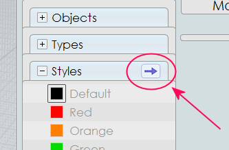
Styles - for organizing objects into different colored categories. This section allows you to work on all objects that have been assigned a particular style. You can assign a style to the selected objects by either clicking on the style line in the properties panel, or by clicking on the colored swatch of a style item within the scene browser. Style assignments will become material assignments when you export to OBJ or LWO mesh formats.
The default set of styles can be altered by setting up a 3DM file that contains the styles you want to have as the default, and then specifying that file as the startup template file under Options / General / Template file. That will cause the styles (and other per-file settings) to come from that file when MoI starts up or when you do a File / New.
The Styles section also has a menu which can be launched by the arrow on the right-hand side of its header, here:
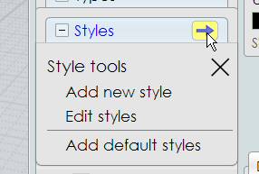
That menu has entries for:
Add new style - brings up a dialog box for entering a name and color for adding a new style to the styles list. The current selection will also be assigned to the new style.
Edit styles - brings up the Edit styles dialog box that allows you to edit the styles list in different ways including adding new styles, deleting styles, editing the name and/or color of an existing style and moving styles up and down in the list.
Add default styles - adds in the set of default styles to the current model, either from the standard default, or from the template file if you have specified a startup template under Options / General / Template file. You can use this if you are working on a model that someone else has sent to you, and you want to bring in all the styles that you normally use.
There are some shortcuts available for editing styles:
- In the Edit styles dialog, right-clicking on a style works as a shortcut for selecting it and pushing the "Edit" button.
- On a scene browser swatch, Ctrl+left click will pop up the color picker as a quick way to edit a style's color.
- On the properties panel, right-clicking on the style line will pop up the Edit style dialog and let you edit the name and/or color of that style.
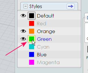
You can control which style is applied to newly drawn objects by setting the "Active style". You can set a style as the Active style by right-clicking (or left-clicking when there is nothing selected) on the style's color swatch.
The active style is marked in the scene browser style list by an extra ring around its color swatch. For example here the Green style is marked as the Active style:

Scene browser items
Every item listed under a scene browser section represents a category of objects, and you can click on different parts of the item to perform an action on all objects that belong to that category.
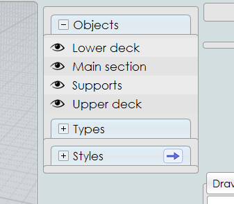
For example here the Objects section is showing 4 items, each of which represents a different group of named objects in the model:
When you move the mouse over each item you will see different clickable areas highlight.
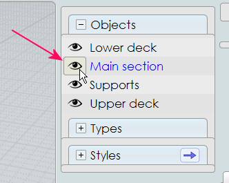
There is a status indicator area on the left:
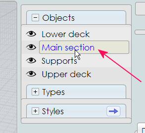
And a name label area on the right:
Style items have an additional color swatch area in the middle:
The status indicator can be used for hiding, showing, or locking objects. The name label can be used for selecting or deselecting, and the color swatch for style items can be used for assigning the current selection to that style or to set the style used for newly drawn objects.
The status indicator will display an eye icon if all the objects belonging to that category are set to be shown, or a blank spot if all the objects belonging to that category are hidden. For example here all the objects belonging to "Lower deck" are shown, and all the objects belonging to "Upper deck" have been hidden:

You can switch a category between hidden and shown by clicking on the status area.
You can also right-click on the status area to "isolate" that item, which will hide everything else leaving just that item being shown. Right-click on it a second time later on to show everything.
You can press and hold the mouse button down and swipe over the status area of several adjacent items to set multiple items in one mouse action.
The status area also shows whether items are locked. If all objects belonging to that item are shown and locked, a lock icon will be displayed instead of the eye. If all of that item's objects are hidden and locked, a fainter lock is displayed, for example:

To switch between locked and unlocked, hold down the Ctrl key and click on the status area.
The status area will also show a mixed state indicator if the item's objects have a variety of different states. If some of the item's objects are shown, and some are hidden, a half-eye icon will be displayed. If there is a mixture of some locked and some unlocked objects, there will be a diagonal dividing line with both an eye icon portion and a lock icon portion. To clear this kind of mixed lock state, hold down Ctrl and click:

You can also use the name area of the item to perform selection actions.
You can select all the objects belonging to an item by clicking on the name label. This will also show any hidden objects - hold the Shift key when clicking to only select currently shown objects.
You can deselect all the objects belonging to an item by holding down the Ctrl key and clicking on the name label area.
You can also right-click on the name label to make that item the "isolated selection", where it will become the only selected thing, with any other existing selection on other objects cleared.
The orientation picker is used in several commands (CPlane, Orient, Import part, Paste part) that need to specify a base point and x/y/z axis orientation.
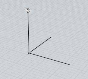
The orientation is represented visually by a base point with 3 perpendicular axis lines, sometimes with one axis (called the "primary axis") marked with an extra outlined dot at its end:
The orientation defines a localized coordinate system with its own position and rotation.
Picking an orientation is a 2 step process.
The first step is to pick the origin point. During this step the z axis of the picker will align itself to a surface normal if the origin point is being snapped on to an existing object. For example:


In addition to surface normals, the picker can also align itself to the plane of a circle or rectangle curve when snapped to their center points, or to the tangent of a curve when snapped to a point on a curve.
This alignment can be disabled by unchecking the "Align to objects" option, or the direction can be reversed by checking the "Flip aligned z axis" option.
After the origin point has been placed, the second step is to optionally adjust the axis directions to control what they are pointing towards.
When you are done adjusting the directions (or if the default directions were already fine), right-click or press the "Done" button to finish picking the orientation.
An axis direction can be adjusted by moving your mouse to the axis line, and dragging on that axis, keeping the mouse button held down and releasing it over the target location you want it to point towards.
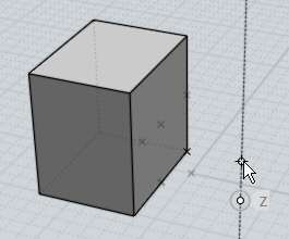
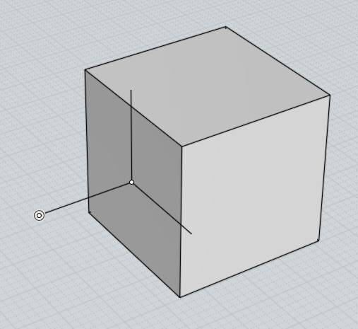
Here's an example - say you have placed the origin point on the side of a cube like this:
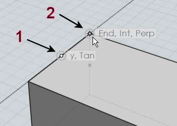
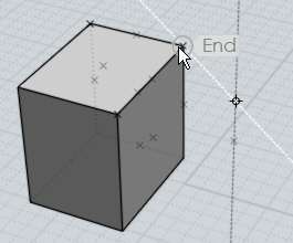
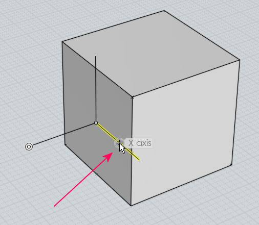
If you would like to adjust the orientation so that the x axis is pointing towards a corner of the cube instead, you can do that by moving your mouse to the x axis line (labels will be displayed on each one as you move over them to indicate which one is which), like this:
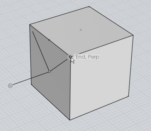
Then press and hold the mouse button down and drag on that axis line. As you drag the picker will adjust that direction to point towards what you are dragging over. Release the mouse button when you are over the desired target point:
The "primary axis" is the axis line that is marked with an extra outline dot at its end. When you drag one of the other axis lines, its motion will be restricted so as to only pivot around the primary axis, keeping the primary axis unmodified.
You can switch the primary axis to a different axis line by clicking on the axis line rather than holding the mouse button down and dragging on it.
If the picker was aligned to an object when picking its initial origin point, the z axis will start out as the primary axis. Otherwise the first axis that is repositioned will become the primary axis.
You can also drag on the origin point to relocate it during the axis adjustment step as well as dragging on the axis lines.
In MoI you can control how newly drawn objects are oriented by either setting the construction plane using View/CPlane, or by snapping points directly on to existing surfaces.
Drawing and snapping directly on to surfaces is made up of a few related pieces.
First, there is an "On srf" object snap that lets you snap a point directly on to the surface that is under the mouse.
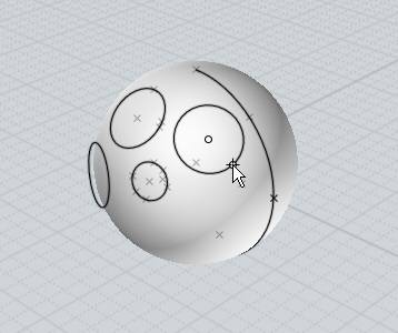
Another related area is surface normal snapping - this is an additional kind of straight snap similar to perpendicular or tangent snaps, except coming off of a surface. For example here the first point of the cylinder was placed on the sphere, then when picking the second point, a surface normal snap is available:

To avoid over-snapping, there will only be one surface normal straight snap line at a time. If your base point is snapped on to an area common to more than one surface (for example the corner of a box), you will only get a surface normal snap if just one of those surfaces is selected.
The last piece of on-surface drawing is surface snap plane alignment. This is when a surface gets used as a temporary construction plane for a drawing command, aligning the drawn object to the surface instead of to the default world x/y/z planes. Some examples:

Snap plane alignment will only happen when you are picking points in the 3D view. Using your mouse in the 2D Top/Front/Right views will keep alignment to the regular view plane.
Different commands align to surfaces with slightly different intensities. The draw commands that are symmetrical around a center point like Circle from center, Rectangle from center, Polygon center, and Polygon Star, will align to a surface if just their initial center point is snapped on to any surface, including both planar and curved surfaces.
Most other commands such as Line, Polyline, Rectangle, Curve, etc... will only align their snap planes (which for example with Polyline controls which direction straight snaps will go in) if you have both the base point and the current point snapped on to a planar (not curved) surface.
If the base point and the current point are snapped on to areas that are common to more than one planar face (like with both points snapped on to an edge of a box so that the points touch 2 faces of the same box), then the planar face that is pointing most towards the eye point direction will be used. So for example if you snap one point on to a corner of a box, rotate the view so that you are facing more towards the face of the box you want to draw on to control which face will be used when there are multiple candidates.
You can type in an expression or formula into numeric edit fields that are asking for distance or radius values.
For example when you are drawing a circle for the radius you can type 15/4*2 and the result 7.5 will be calculated for you.
Another example is if you're drawing a line, you can type <360/12 to set an angle constraint of 360/12 = 30 degree angle snap for that line.
You can also use functions like sin - for example typing in sin(45) will calculate the sin of 45 degrees. All trig functions take angles in degrees. Angle input in radians is available by prefixing the function name with an underscore character, for example: _sin(PI/4). Any of the functions on the JavaScript "Math" object are available for use, including: sin(), cos(), tan(), sqrt(), pow(), round(), random(), the constant PI, and also rad() which takes a parameter in degrees and returns it in radians, and deg() which takes a parameter in radians and returns it in degrees.
You can also type in a "relative expression" to modify the value of an edit field that has previously been initialized to some other value. To make a relative expression, start it with one of these symbols: + -- * / which will alter the value by the given amount rather than inputting a completely new value. So for instance in a grid size input field you can type /2 to modify the existing value by dividing it by 2. Note that for subtraction a double minus sign is used to avoid any conflict with entering in a regular non-relative negative value.
You can also use expressions for x,y,z point values. If your regional settings for the operating system uses a comma character as the decimal point separator for numeric values, then surround each coordinate with parentheses to separate them, for example: (2+2)(5/2-1)(5).
© 2010 Triple Squid Software Design
Back to reference index Prev page
© 2010 Triple Squid Software Design