Back to reference index Prev page
Misc
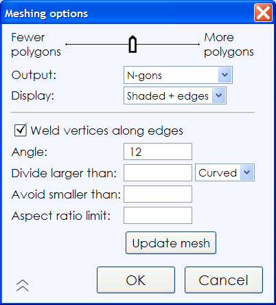
When saving to a polygon file format, MoI needs to convert from smooth surface data into faceted polygon data. The "Meshing options" dialog is shown during this process to control different aspects of how the polygon data is generated.
During the meshing process the number of generated polygons and points are displayed in the upper-right corner of the main window where command options normally are shown.
MoI does extra work to align mesh vertices along shared edges between joined surfaces. So you'll generally want to make sure surfaces that are next to one another have been joined together into one connected solid object before exporting mesh data.
Initially the dialog is shown in its compact form:

Move the slider to the left to create a lighter mesh with fewer polygons. This will reduce the amount of data generated but will also give a more jagged appearance to the mesh. Move the slider to the right to create a denser mesh with more polygons in it. A denser mesh will be smoother visually but will also contain a lot more data.
The Output: option controls the type of polygon data that will be created, whether to allow creation of N-gons (polygons with more than 3 or 4 sides), or whether to break polygons up to only allow 3 or 4 sided polygons. Some programs have difficulty dealing with complex N-gon shapes. If you see bad results when importing N-gons into your polygon application, try reducing this option to Quads & Triangles, or Triangles only. Some polygon file formats don't allow N-gons, for example STL or 3DS files can only contain triangles, so you won't see this option when exporting to these formats.
You can click on the arrow in the lower-left corner of the compact dialog to expand it to show more options:
Weld vertices along edges option:
Welding controls how polygons are connected to points along shared edges between surfaces. When welding is on, polygons will share a single point in common along the shared edge. When welding is off, the polygons on each side of the edge will have their own individual points which are stacked up in the same location.
Example of welded polygons - each polygon from either side of a joined edge will be hooked into the same vertex. The vertices are shared between polygons:

Example of unwelded polygons - in this case each polygon across the unwelded edge has its own individual vertices. The points are stacked on top of each other, shown slightly separated here for illustration: 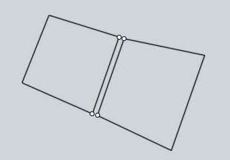
Typically welding is left on for normal rendering use but some programs may have difficulties with welded meshes. Also, sometimes you may want to have points unwelded for certain special effects, such as doing a sketch or toon style rendering. Unwelded edges will get an accent line in a sketch rendering. Turning welding off may also help separate polygons out into different chunks for each original surface during later polygon editing.
Angle option:
The Angle option controls the maximum angle allowed between the surface normals at the corners of each polygon. When the maximum allowed angle is small, it will force additional subdivisions along more tightly curved areas. When the maximum angle is larger, fewer subdivisions will be forced in curved areas and coarser polygons will be allowed. This is the same value that is controlled by the slider. This option just allows you to control it more directly and to allow for values outside of the normal slider range. For example, if you want a very low polygon mesh you may want to type in a larger angle here than the slider normally permits.
Divide larger than option:
The "Divide larger than" option provides another way to refine the mesh in certain areas. You can enter a distance here which will force polygons that are larger than this length to be broken down into smaller pieces. This can be used to add detail to larger areas that have shallow curvature. Areas that have shallow curvature will tend to get fewer polygons in them because the regular density control that is adjusted by the slider is based only on curvature and not lengths. You can also adjust the drop-down to limit additional subdivisions to a specific type of surface. By default it will be applied only to curved surfaces leaving planar surfaces unaffected, but this can be changed to only apply to planar surfaces for special meshing needs, or to apply to all surfaces.
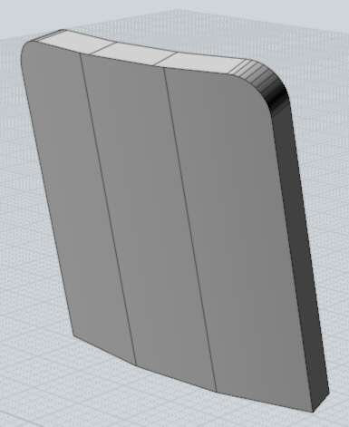
Here is an example of a large area with shallow curvature that didn't get many polygons. Because it is covering a larger area the lack of refinement here can be more noticeable:
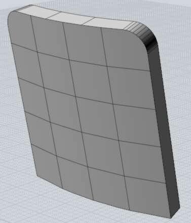
By entering a distance of 5 in the "Divide larger than" option, it will force more divisions along the large shallowly curved surface. Any polygon larger than 5 units along an edge will be further broken down:
Avoid smaller than option:
The "Avoid smaller than" option can be used to avoid creating too many polygons in small areas where they may be difficult to see, in order to reduce polygon counts. You enter a distance here, and subdivisions will be restricted for any polygon that is smaller than this value. Normally the same density will be generated in both small and large areas because it is controlled only by the curvature. This is good if you are going to be zooming into a smaller area for a rendering, but if you're never going to zoom in to a small area you may wish to have fewer polygons there to reduce the amount of data being processed and speed things up.
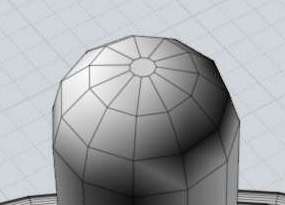
Here's an example of a knob that is a tiny piece of a much larger model:
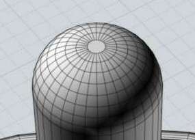
By setting an "Avoid smaller than" distance of 0.5, it will reduce the number of divisions there since this knob is close to that size:
Aspect ratio limit option:
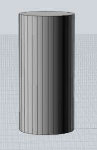
The "Aspect ratio limit" option offers another way to force additional subdivisions for quads that are short in one direction but long in another. This affects all surfaces, including planar ones. Here is an example of a mesh with long and skinny quads:
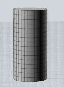
If you want to get more regularly sized quads here, you can enter 2 in the aspect ratio control, which will force a division in any quad that has one edge more than twice as long as the other:
After entering a value into one of the extended controls, you need to click the "Update mesh" button to see the change reflected on the screen. It doesn't do it automatically since it can be fairly time consuming to create the mesh, and you may want to tweak several of these values a little bit before doing the update.
Once you enter a value into one of the extended controls, you can clear it by either using backspace to clear the field or by entering a value of 0.
It is possible to set up a keyboard shortcut to do an incremental save, where a number in the filename will be bumped on each save, like file01.3dm, file02.3dm, file03.3dm, etc...
To do this, go to Options / Shortcut keys, and add a new entry with a key of whatever you like (for example, Alt+S), and IncrementalSave for the command.
You can repeat the most recently used command by right-clicking inside a viewport or by pushing the Enter key on the keyboard.
It is also possible to turn on repeat automatically for a period of time by clicking the "Repeat" checkbox that shows up at the bottom of the command options area in the upper-right area of the window. When that option is checked, a drawing command will automatically repeat until you cancel it or uncheck that box.
Construction lines allow you to quickly place additional guide lines to help with precise snapping and alignment while drawing shapes.
You can create a construction line anytime that MoI is asking you to specify a point location, like for the start or end of a line, the center of a circle, the next point of a curve, etc... To create a construction line, hold down and drag the mouse.
When MoI is asking you for a point, clicking and releasing the mouse button will finish picking that point. If you hold the button down and drag instead of releasing, you will drag out a construction line. Construction lines are automatically erased at the end of each command.
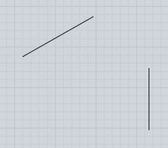
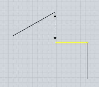
Here is an example of how a construction line can be used to help accurately place a point. Imagine you have a drawing as shown here in the first image, and you want to create a new horizontal line as shown in yellow in the second image, such that the end is exactly aligned as indicated by the dashed line:
To draw such a line, start the line command and click the first point at the end that you can easily grab:
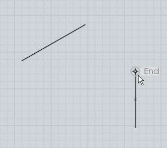
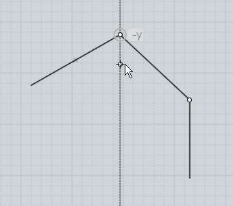
Next, move to the end that you want to be aligned with. Click down on that point, but do not release the mouse button. Instead hold the button down and drag away and a construction line will be created. Drag downward to make the construction line go downward, and release the mouse when you see the construction line has snapped vertically:
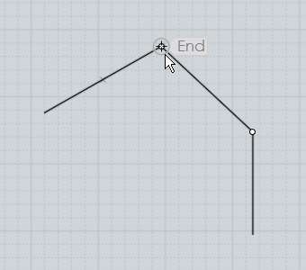
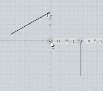
Now that a construction line has been created dropping down from that point, you can find a snap point at the intersection between the horizontal line and the vertical construction line, and click it to place the end of the line:
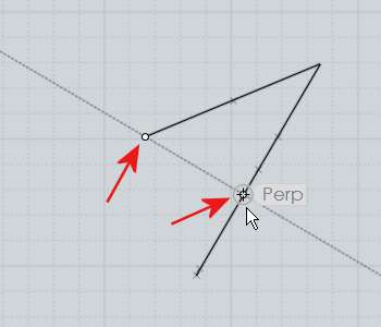
You can drag out any number of these construction lines to set up additional intersection snaps. They can be dragged along the x, y, or z axes, perpendicular or tangent from a curve, etc... The construction line is formed through 2 points - the point you started the drag on and then the point where you release the mouse. After a construction line has been defined by these 2 points, the midpoint between them is available as another snap as well as the reflected endpoints. The reflected endpoints are calculated by taking the distance between the start and end and repeating that same distance in both directions. For example, creating a construction line through the 2 points in the first image will provide the additional snaps shown in the second image:
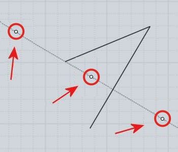
This makes it possible to find the midpoint between any 2 points by dragging a construction line through those 2 points. Also the reflected endpoints can be useful for snapping symmetrically around a centerline.
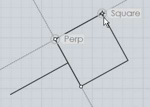
Here is an example of how the reflected endpoints can be useful. Let's say you have a line, and you want to draw a square at the end of the line, centered around it, like so:
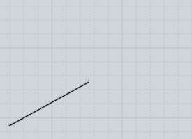
To do this, start the Rectangle 3 points command. Before placing any points for the rectangle, go to the end of the line and drag out a construction line perpendicular to it:
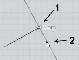
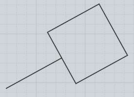
Thanks to the reflected endpoints, this now sets up all the snaps you need to draw the square. Place the first point at the original end of the construction line, point #2 marked above. Then for the next point of the rectangle, pick the reflected endpoint on the other side:
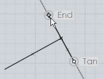
Finally, the square snap built into the rectangle tool can be used for placing the 3rd point to form an exact square:
Construction lines can be used in this manner to form a kind of quick temporary scaffolding or grid adapted to the size and orientation of existing objects.
After you drag out a construction line, a small marker will appear above your mouse pointer that looks like this:
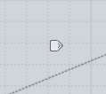
If you move your mouse over that marker the marker will brighten up and if you press and hold down on the marker for a moment a menu will pop up with additional options for controlling the construction line:

The "Relocate cline" option allows you to pick a new point for the construction line to go through, basically dragging the construction line to a new location. This allows you to capture a direction and then move it to a different area to use for a parallel construction guide.
The "Reorient cline" option allows you to pick a new point and pivot the construction line to point in a new direction going through that point. The original endpoints, midpoint, and reflected endpoints of the construction line are still available as snaps at the same distances after the reorientation. This, combined with the relocation option, allows you to use a construction line as a kind of measuring stick to capture a distance between any 2 snapped points and then apply that distance to a different area or different direction.
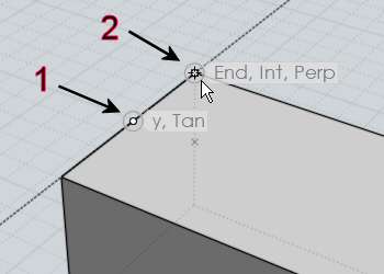
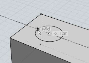
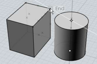
Here is one example of measuring a distance and applying it in a different direction while drawing a cylinder on top of a box. After starting the cylinder command, a construction line is created from the midpoint of the box's edge to the end:
Then the construction line is re-oriented to point perpendicular to the edge, towards the inside of the box:
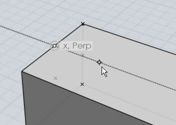
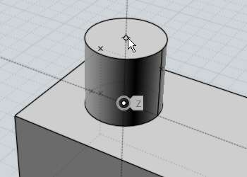
Now there are snap points available at the same spacing as the edge of the box to draw an exactly placed cylinder:
The "Rotate cline" option allows you to rotate the construction line around its base point by the given angle. This allows you to set up a guide line at the given angle relative to some existing edge of an object. It is also possible to use Distance or Angle constraint while initially drawing the construction line by dragging outside the viewport to the distance or angle controls and clicking and entering a constraint value there, then returning to the viewport and clicking to place the second point of the construction line.
The "Division snap" option enables you to snap to different fractional increments along the construction line instead of only the midpoint. For example, entering 5 here will provide snaps at 1/5, 2/5, 3/5, 4/5, as well as -1/5, -2/5, 6/5, 7/5, etc...
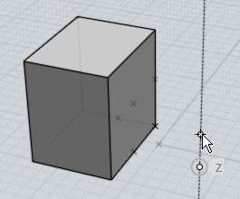
The "Project next pt" option forces the next picked point to be projected to the closest point along the construction line. This allows you to snap on to a different object and find the relative height of that point along the line. For example, here a construction line has been pulled up in z along side of a different object. When projection is turned on you can move to a snap point on the other object and the relative height of that object will be captured by the projection on to the line:
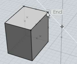
Here is an example of this projection being used to place the top point of a cylinder at an equal height as an existing box object:
Keys or key combinations can be assigned to different actions under Options / Shortcut keys.
The Enter and Esc keys have predefined functions. You can use Enter as a shortcut for clicking the "Done" button while inside of a command, and pressing it outside of a command will repeat the last used command. Esc is used to cancel or turn off modes. If you are currently running a command, Esc will cancel the command same as clicking the "Cancel" button. If you are outside of a command, Esc will deselect objects on the first tap, and then turn off any points that were enabled with the "Show pts" command on the next tap.
To create a new shortcut key, click the "Add" button and then fill in the entries for Key and Command.
The key can be defined using a letter (like "A") or one of these labels: F1 - F12, UpArrow, DownArrow, LeftArrow, RightArrow, Home, End, PageUp, PageDown, Insert, Delete, Backspace, Space. The key can be prefixed by one or more of these modifiers: Ctrl+ , Shift+, or Alt+ .
Examples of some key assignments:
| A |
= push the A key with no other modifier keys. |
| Ctrl+A |
= hold down Ctrl and push A |
| Ctrl+Shift+A |
= hold down both Ctrl and Shift and push A. |
| Ctrl+UpArrow |
= hold down Ctrl and push the Up arrow. |
The Command can be filled in with either the name of a command, or a script macro. Script macros are prefixed with the keyword "script:".
Command names:
AddPoint, Align, Arc3pt, ArcCenter, ArcContinue, ArcTangent, ArrayCircular, ArrayCurve, ArrayDir, ArrayGrid, Blend, BooleanDifference, BooleanIntersection, BooleanMerge, BooleanUnion, Box, Box3pts, BoxCenter, Chamfer, Circle, Circle3pt, CircleDiameter, CircleTangent, Cone, Copy, CopyClipboard, Curve, Cut, Cylinder, Delete, Ellipse, EllipseCorner, EllipseDiameter, Export, Extend, Extrude, Fillet, Helix, History, Image, Import, IncrementalSave, InterpCurve, Intersect, Join, Line, Loft, Mirror, Move, Network, New, Offset, Open, Paste, PlanarSrf, Plane, Plane3pts, PlaneCenter, Point, Polygon, PolygonEdge, PolygonStar, Polyline, Project, RailRevolve, Rect3pts, Rectangle, RectCenter, Revolve, Rotate, RotateAxis, Save, SaveAs, Scale, Scale1D, Scale2D, Separate, Shell, ShowPoints, ShrinkTrimmedSrf, SketchCurve, Sphere, Sweep, Text, Trim
So for example, a shortcut for E to activate extrude would look like this:
E Extrude
There are a few buttons in the UI that run script macros instead of commands: Hide, Reset all, Select all, Deselect all, and Invert. This is so they can be used while a command is still running, so these functions are slightly different than a regular command. To hook these up to a shortcut key fill in the Command part with one of the following scripts:
Hide:
script:moi.geometryDatabase.hide();
Reset all views:
script:moi.view.resetAll();
Select all:
script:moi.geometryDatabase.selectAll();
Deselect all:
script:moi.geometryDatabase.deselectAll();
Invert selection:
script:moi.geometryDatabase.invertSelection();
Here are some frequently requested scripts that can be assigned to a key to perform a custom action. To use these, copy the entire line that begins with script: and paste it into the Command part of the shortcut key:
Maximize the view the mouse is over, or switch back to split view (usually assigned to Space key):
script:if ( moi.ui.mainWindow.viewpanel.mode != 'split' ) { moi.ui.mainWindow.viewpanel.mode = 'split' } else { var viewport = moi.ui.getViewportUnderMouse(); if ( viewport ) { viewport.viewPanel.mode = viewport.name } }
Go to split view:
script:moi.ui.mainWindow.viewpanel.mode = 'Split';
Maximize the 3D view:
script:moi.ui.mainWindow.viewpanel.mode = '3D';
Maximize the Front view:
script:moi.ui.mainWindow.viewpanel.mode = 'Front';
Maximize the Right view:
script:moi.ui.mainWindow.viewpanel.mode = 'Right';
Isolate the selection (hide everything else that is not selected):
script:moi.geometryDatabase.invertSelection(); moi.geometryDatabase.hide(true);
Select all curve objects:
script:moi.geometryDatabase.getObjects().getCurves().setProperty( 'selected', true );
Select all open curves (curves that do not form a closed loop):
script:var curves = moi.geometryDatabase.getObjects().getCurves(); for ( var i = 0; i < curves.length; ++i ) if ( !curves.item(i).isClosed ) curves.item(i).selected = true;
Hide all curve objects:
script:moi.geometryDatabase.getObjects().getCurves().setProperty( 'hidden', true );
Hide all surface/solid objects:
script:moi.geometryDatabase.getObjects().getBReps().setProperty( 'hidden', true );
Select all objects that were created by the last command:
script:var a = moi.command.lastCommandRevisionStart; var b = moi.command.lastCommandRevisionEnd; var objects = moi.geometryDatabase.getObjects(); for ( var i = 0; i < objects.length; ++i ) { var obj = objects.item(i); if ( obj.databaseRevision > a && obj.databaseRevision <= b ) obj.selected = true; }
Toggle grid snap on or off:
script:moi.drawingAids.gridSnap = !moi.drawingAids.gridSnap;
Toggle object snap on or off:
script:moi.drawingAids.objectSnap = !moi.drawingAids.objectSnap;
Toggle straight snap on or off:
script:moi.drawingAids.straightSnap = !moi.drawingAids.straightSnap;
Toggle the light direction:
script:var dir = moi.view.lightDirection; if ( dir.x == 1 && dir.y == 1 && dir.z == -1 ) { dir.set(-0.5,1,0); } else { dir.set(1,1,-1); } moi.view.lightDirection = dir;
Many other scripts are possible, see the web site for a larger list, and post any requests for custom scripts to the discussion forum.
Back to reference index Prev page
© 2007 Triple Squid Software Design